54
www.cooperbussmann.com/wirelessresources
Cooper Bussmann 915U-2 Wireless Mesh I/O and Gateway User Manual
Rev Version 1.2.2
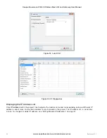
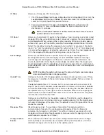
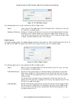
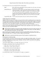
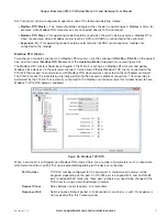
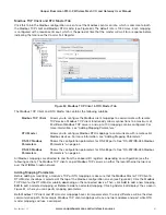
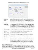
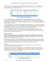
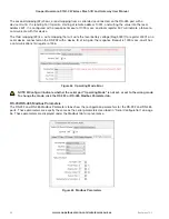
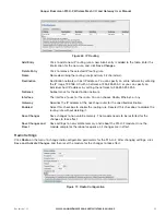
Figure 50 Fail-safe Block Analog
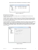
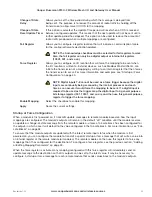
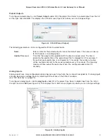
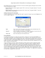
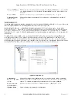
In the example shown in Figure 51, digital outputs 1–8 will be initialized on startup (turned on) and then start the fail
timeout countdown from 60 seconds after which time the outputs will be set to the fail value (off) unless the output
is updated.
Figure 51 Fail-safe Block Digital
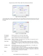
First Register
Starting register to which the fail-safe block applies.
Fail Timeout
Time period before the fail-safe state will be activated.
Count
Number of outputs to which the fail-safe block applies.
Initialize at Startup
Indicates the outputs will be initialized when the module is first powered on. Used in
conjunction with the preset value.
Preset Value
Value the registers are set to when the module is powered on and the “Initialize at
Startup” checkbox is selected. If a digital value is selected, the preset value will be
either on or off. If an analog value is selected the preset value will be a value between
0 and 65535.
Invalidate on Fail
When selected, the value is set to a null or invalidated value (~) if an update is not
received before the fail timeout period expires.
Fail Value
Value that the registers are set to if an update is not received before the fail timeout
period expires and the “Invalidate on Fail” checkbox is not selected. If a digital value
is selected the preset value will be either On or Off. If an analog value is selected the
preset value will be a value between 0 and 65535.
Apply
Saves the settings.

