www.cooperbussmann.com/wirelessresources
Cooper Bussmann 915U-2 Wireless Mesh I/O and Gateway User Manual
11
Rev Version 1.2.2
C
hapTEr
2 - INSTaLLaTION
2.1 General
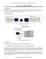
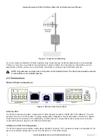
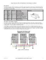
The 915U-2 Series modules are housed in a plastic enclosure with DIN rail mounting, providing options for up to
14 I/O points, and separate power and communications connectors. The enclosure measures 170 x 150 x 33 mm,
including the connectors. The antenna protrudes from the top.
2.2 Power/Supply
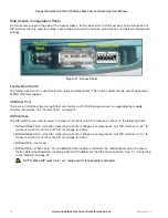
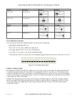
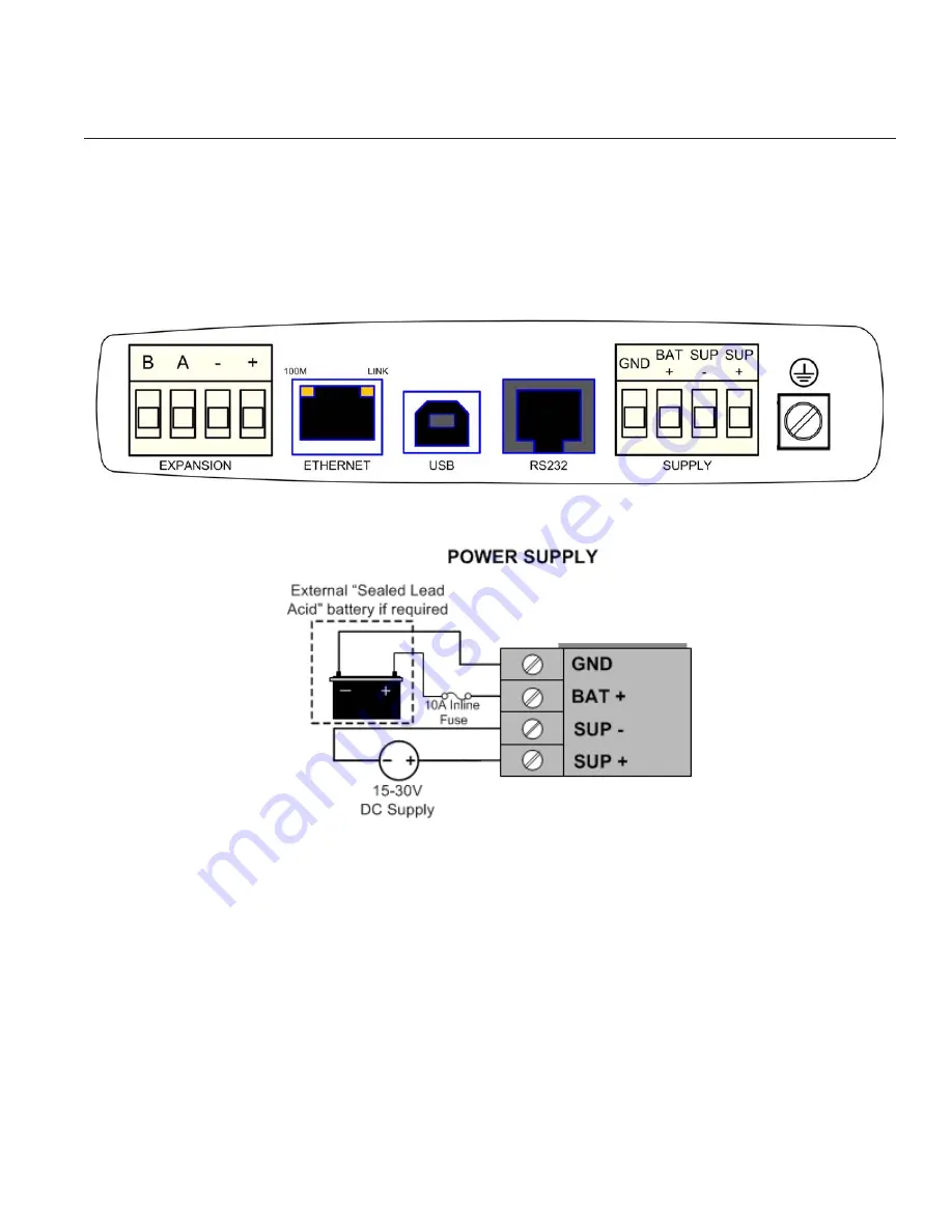
Figure 2 Power Connectors
Figure 3 Supply Connections
Requirements
There are two recommended power options available for the 915U-2 module:
• 15–30 Vdc power source rated at 37W, connected to the SUP+ and SUP- terminals
• 12–15 Vdc power source rated at 24W, connected to the BAT+ and GND terminals
A primary power supply connected to the SUP+ and SUP- terminals automatically charges a 13.8V sealed lead-
acid battery, if connected to the BAT+ and GND terminals at up to 1A at ambient room temperature (25°C). Battery
charge current is reduced to 0.5A at 60°C. If using a battery, it is recommended that a 10A inline fuse be fitted as
prevention against battery short circuit.
If you are using the first option and the primary supply fails, the battery supply will continue to power the module
without interruption to the operation. The supply and battery charging terminals are hosted on the 4-way connector
on the bottom edge of the module labeled “Supply.” Both the supply and battery connections have reverse polarity
and over-voltage protection.


