
www.cooperbussmann.com/wirelessresources
Cooper Bussmann 915U-2 Wireless Mesh I/O and Gateway User Manual
95
Rev Version 1.2.2
a
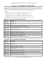
ppENDIx
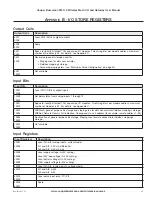
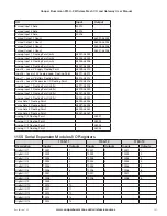
B - I/O STOrE rEGISTErS
Output Coils
Output Coils
Description
0001
0008
Local DIO1–DIO8 as digital outputs
0009
0020
Spare
0021
0500
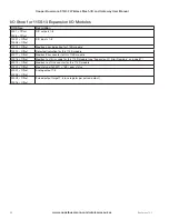
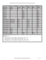
Space for locally attached 115s expansion I/O modules. Twenty register per module address, maximum
number of modules is 24. For details, see Appendix C.
0501
3000
General purpose bit storage used for:
• Staging area for data concentrator
• Fieldbus mappings storage
• Force mapping registers (see “Startup or Force Configuration” on page 45)
3001
10000
Not available
Input Bits
Input Bits
Description
10001
10008
Local DIO1–DIO8 as digital inputs
10009
10020
Set point status from analog inputs 1 through 12
10021
10500
Space for locally attached 115s expansion I/O modules. Twenty registers per module address, maximum
number of modules is 24. For details, see Appendix C.
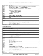
10501
10595
WIBMesh: general purpose bit storage and staging area for data concentrator fieldbus mappings storage.
WIBNet: Remote Comms Fail indication. Corresponds to unit address (for example, remote address 1–95).
10596
12500
Continuation of general purpose bit storage. Staging area for data concentrator fieldbus mappings
storage.
12501
30000
Not available
Input Registers
Input Registers
Description
30001
30004
Local AI1–AI4 (analog inputs, current mode)
AI1 and AI2: 4–20 mA differential
AI3 and AI4: 4–20 mA sink
30005
30006
30007
30008
Local supply voltage (0–40V scaling)
Local 24V loop voltage (0–40V scaling)
Local battery voltage (0–40V scaling)
115S supply voltage (0–40V scaling)
30009
Local AI1–AI4, (analog inputs, voltage mode)
30012
AI1 and AI2: 0–20V
AI3 and AI4: 0–5V
30013
30016
Local pulse input rates: PI1–PI4
30018
30020
Spare


