www.cooperbussmann.com/wirelessresources
Cooper Bussmann 915U-2 Wireless Mesh I/O and Gateway User Manual
63
Rev Version 1.2.2
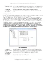
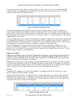
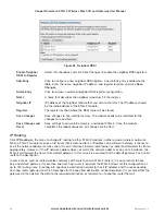
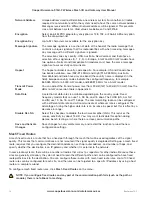
these values into its own local registers, starting at 40501. The server port is 502, which is a standard Modbus
TCP port address. If the mapping fails to communicate to the TCP server, it will write a value of “1” into local
register 508, indicating a communications failure.
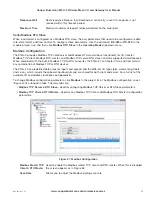
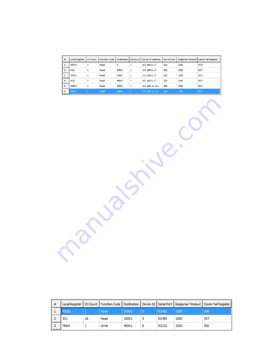
Figure 62 Modbus TCP Mapping Table
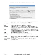
The second mapping (#2) shows something similar, but instead of analog values, the values are digital. The
Function code is “Read” from IP address 192.168.0.17 and device ID #10. It will read eight values starting from
address 10001, and write them to the local address, starting at 501. Again, it is using the same server port of 502. If
the mapping fails to communicate to the TCP server, it will write a value of “1” into local register 507, indicating that
mapping failed to communicate.
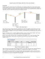
The third mapping (#3) is similar to the second mapping, but instead of reading from the local Ethernet subnet (LAN)
it is reading from an IP address on the radio network (another 915U-2 module). The Function code is “Read” from
IP address 192.168.10.101 and device ID #1. It will read four values, starting from address 10001, and write them to
the local address, starting at 509. A Comms Fail register is configured at local register 506.
The fourth mapping (#4) is configured to write the values from the local analog input #1 and #2 across to a
TCP server at IP address 192.168.0.17. It will write the values into the destination address 40001 and 40002 at
device ID of 10. It is using the TCP server port 502 and is configured with a response time of 1000 msec. If it fails
to communicate, it will turn on local register 505.
Modbus RTU Master
Modbus RTU functionality allows connections to Modbus RTU slave devices via the RS-232 or RS-485 ports. The
maximum number of mappings that can be configured is 100. All Modbus mappings are directed to or from the
onboard I/O registers depending on the configuration (described below). The Modbus RTU master polls the slave
devices via the serial port configured in the mappings.
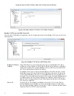
Modbus RTU (serial) devices can also be polled if connected to remote 915U-2 serial ports. To enable this feature
the remote 915U-2 serial port must be set to “Modbus RTU Master” mode and the TCP mappings must reflect the
correct server IP address and port number of the remote 915U-2. Polling TCP servers or RTU slaves over the radio
network will greatly increase radio communications and is not recommended for busy systems.
Example
The Modbus RTU mapping is very similar to the Modbus TCP mapping except that the destination is a serial
interface instead of an Ethernet address and port.
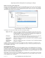
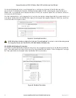
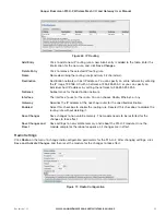
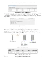
In the example in Figure 63, the first mapping (#1) shows a read mapping from a serial device connected on the
RS-485 port with a device ID of 5. It is reading one I/O point, starting at remote address 30001, and writing the
value into the local address 40501. It is configured with a response timeout of 1000 msec, and local register 508
will indicate a failure to communicate with this device.
Figure 63 Modbus RTU Example

