30
www.cooperbussmann.com/wirelessresources
Cooper Bussmann 915U-2 Wireless Mesh I/O and Gateway User Manual
Rev Version 1.2.2
modules, or even behind one of the modules if the repeater module is installed at a high location (for example,
a tower, or mast). Repeater modules can have their own I/O and act as a normal 915U-2 module within the
system.
Design for Failures
All well designed systems consider system failure. I/O systems operating on a wire link will fail eventually, and the
same is true for a radio system. Failures can be short-term, such as interference on the radio channel or power
supply failure, or long-term, such as equipment failure.
The modules provide the following features for system failure:
• Outputs can reset if they do not receive a message within a configured time. If an output should receive an
update or change message every 10 minutes and it has not received a message within this time, some form
of failure is likely. If the output is controlling machinery, it is good design to switch off the equipment until
communications are re-established.
• The modules provide a fail-safe feature for outputs. This is a configurable time value for each output. If a
message has not been received for this output within the configured time, the output will assume a configured
value. We suggest that this reset time be a little more than twice the update time of the input. It is possible
to miss one update message because of short-term radio interference. However, if two successive update
messages are missed, long term failure is likely and the output should be reset. For example, if the input
update time is three minutes, set the output reset time to seven minutes.
• A module can provide an output that activates on communication failure to another module. This can be used
to provide an external alarm indicating that there is a system fault.
Indicating a Communications Problem
Communications problems can be indicated using fail-to-transmit alarms or fail-to-receive alarms. These alarms
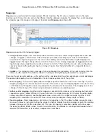
can be configured using the Mapping screen within the MConfig Utility (see “Mappings” on page 42).
•
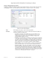
Fail-to-transmit Alarm
—The first method is to setup a communications indication on a register of your
choice when configuring a mapping. This can be done using an existing mapping (no need to setup a special
communications mapping). When entering a block write or gather/scatter mapping, enter a register location
for a communications failure in the Fail Register field. This register can be a local DIO (Reg 1–8) or an internal
register. Whenever the module tries to send this mapping and fails to get a response (ACK) it will turn on the
physical output if using a DIO (reg1-8) to display the alarm, or if using an internal register the value will switch
from “0” to “1.”
The communications failure indication will clear on the next successful transmission of the mapping. This
method will work with any number of repeaters in the link. However, it will only indicate a failure to transmit if
the Acknowledge checkbox is selected in the mapping. It will not provide a fail indication if the mappings are
configured as transmit only (Acknowledge checkbox is not selected).
•
Fail-to-receive Alarm
—The second method is to set up a communications link indication on the receiving
end using normal write mappings on the transmitting end and the fail-safe time function on the receiving end.
Setup a communications mapping from an unused digital input (can be an internal signal, such as supply
fail) and map it to the output that will indicate the communication status. The input will be updated on a time
interval (default is 10 minutes). Reconfigure a time that will provide a good indication of failure (such as 30
seconds), but not update so often that it generates too many communication check messages.
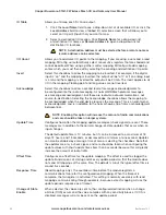
On the receiving end, configure a fail-safe block on the output configured in the above mapping. Configure
a “Fail Time Out” for a little over twice the mapping update time (for example, one minute, and 10 seconds).
Next, configure a Fail Value of “1” to turn on the output when it fails to be updated. Alternatively, you could
invert the mapping so the output is always on, and configure a Fail Value of “0” to turn off the output when not
updated.
This method will work with any number of repeaters in the link. You should use separate outputs to indicate
“Comms OK” of different remote modules.

