9
2.2 LED Indicators
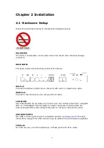
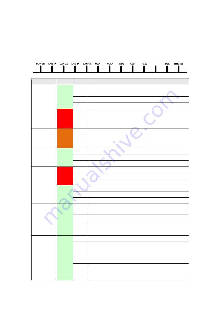
The front panel LED indicators are shown below and explained in the following table.
This information can be used to check the status of the device and its connections.
LED
Color Mode
Function
POWER
Green
On
The device is powered up.
Off
The device is powered down.
Blink
The device is flashing new firmware.
Red
On
POST (Power On Self Test) failure or other
malfunction. A malfunction is any error of internal
sequence or state that will prevent the device from
connecting to the DSLAM or passing customer data.
Amber On
When the reset button is held in for five seconds to
reset the modem to factory default, the power light
should go amber (blink for 1 second) to indicate
factory reset is ready.
LAN 1X-4X
Green
On
An Ethernet Link is established.
Off
An Ethernet Link is not established.
Blink
Data transmitting or receiving over LAN.
WAN
Red
On
An Ethernet Link is established at 1000 Mbps.
Off
An Ethernet Link is not established.
Blink
Data transmitting or receiving over Ethernet WAN.
Green
On
An Ethernet WAN Link is established at 10/100 Mbps.
Off
An Ethernet WAN Link is not established.
Blink
Data transmitting or receiving over Ethernet WAN.
WLAN
Green
On
The wireless module is ready.
(i.e. installed and enabled).
Off
The wireless module is not ready.
(i.e. either not installed or disabled).
Blink
Data transmitting or receiving over WLAN.
WPS
Green
On
WPS enabled and PC connected to WLAN
Off
WPS disenabled when WPS configured
After clients connected to router about 5
minutes, LED is OFF.
Blink
The router is searching for WPS clients or WPS
un-configured.
FXS
Green
On
FXS phone line is off hook.
Содержание VI-3223u
Страница 1: ...VI 3223u Multi DSL WLAN IAD User Manual Version B1 0 July 19 2013 261099 020...
Страница 7: ...6 1 2 Application The following diagram depicts a typical application of the VI 3223u...
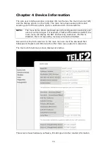
Страница 16: ...15 STEP 3 After successfully logging in for the first time you will reach this screen...
Страница 26: ...25...
Страница 32: ...31 Chapter 5 Advanced Setup The following screen shows the advanced menu options...
Страница 67: ...66 5 11 UPnP Select the checkbox provided and click Apply Save to enable UPnP protocol...
Страница 72: ...71 5 15 1 Storage Device Info Display after storage device attached for your reference...
Страница 74: ...73 Automatically Add Clients With Following DHCP Vendor IDs...
Страница 98: ...97 Click Apply Save to set new advanced wireless options...
Страница 103: ...102 7 1 SIP Basic Setting 7 1 1 Global Parameters A common parameter setting...
Страница 104: ...103 7 1 2 Service Provider This screen contains basic SIP configuration settings...
Страница 106: ...105 7 2 SIP Advanced This screen contains the advanced SIP configuration settings...
Страница 107: ...106 7 2 1 Global Parameters A common parameter setting...
Страница 144: ...143 STEP 6 Click Have Disk and insert the printer driver CD STEP 7 Select driver file directory on CD ROM and click OK...
Страница 146: ...145 STEP 11 Check the status of printer from Windows Control Panel printer window Status should show as Ready...
Страница 172: ...171 Click Next to continue or click Back to return to the previous step...


