119
Option Description
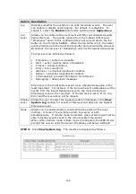
Log
Indicates whether the system is currently recording events. The user
can enable or disable event logging. By default, it is disabled. To
enable it, select the
Enable
radio button and then click
Apply/Save
.
Log
Level
Allows you to configure the event level and filter out unwanted events
below this level. The events ranging from the highest critical level
“Emergency” down to this configured level will be recorded to the log
buffer on the VI-3223u SDRAM. When the log buffer is full, the newer
event will wrap up to the top of the log buffer and overwrite the old event.
By default, the log level is “Debugging”, which is the lowest critical level.
The log levels are defined as follows:
•
Emergency = system is unusable
•
Alert = action must be taken immediately
•
Critical = critical conditions
•
Error = Error conditions
•
Warning = normal but significant condition
•
Notice= normal but insignificant condition
•
Informational= provides information for reference
•
Debugging = debug-level messages
Emergency is the most serious event level, whereas Debugging is the
least important. For instance, if the log level is set to Debugging, all the
events from the lowest Debugging level to the most critical level
Emergency level will be recorded. If the log level is set to Error, only
Error and the level above will be logged.
Display
Level
Allows the user to select the logged events and displays on the
View
System Log
window for events of this level and above to the highest
Emergency level.
Mode
Allows you to specify whether events should be stored in the local
memory, or be sent to a remote system log server, or both
simultaneously. If remote mode is selected, view system log will not be
able to display events saved in the remote system log server.
When either Remote mode or Both mode is configured, the WEB UI will
prompt the user to enter the Server IP address and Server UDP port.
STEP 3:
Click
View System Log
. The results are displayed as follows.
Содержание VI-3223u
Страница 1: ...VI 3223u Multi DSL WLAN IAD User Manual Version B1 0 July 19 2013 261099 020...
Страница 7: ...6 1 2 Application The following diagram depicts a typical application of the VI 3223u...
Страница 16: ...15 STEP 3 After successfully logging in for the first time you will reach this screen...
Страница 26: ...25...
Страница 32: ...31 Chapter 5 Advanced Setup The following screen shows the advanced menu options...
Страница 67: ...66 5 11 UPnP Select the checkbox provided and click Apply Save to enable UPnP protocol...
Страница 72: ...71 5 15 1 Storage Device Info Display after storage device attached for your reference...
Страница 74: ...73 Automatically Add Clients With Following DHCP Vendor IDs...
Страница 98: ...97 Click Apply Save to set new advanced wireless options...
Страница 103: ...102 7 1 SIP Basic Setting 7 1 1 Global Parameters A common parameter setting...
Страница 104: ...103 7 1 2 Service Provider This screen contains basic SIP configuration settings...
Страница 106: ...105 7 2 SIP Advanced This screen contains the advanced SIP configuration settings...
Страница 107: ...106 7 2 1 Global Parameters A common parameter setting...
Страница 144: ...143 STEP 6 Click Have Disk and insert the printer driver CD STEP 7 Select driver file directory on CD ROM and click OK...
Страница 146: ...145 STEP 11 Check the status of printer from Windows Control Panel printer window Status should show as Ready...
Страница 172: ...171 Click Next to continue or click Back to return to the previous step...


