Removal and Replacement
DIGITAL PowerStorm 1000 Graphics Subsystem Owner's Guide 5–9
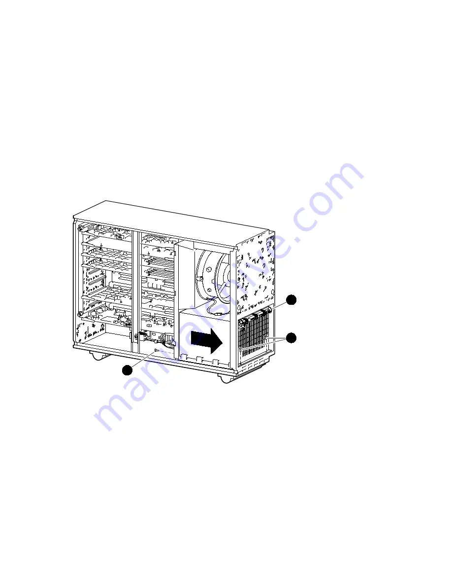
Figure 5-5 Removing the Power Supply
ML014215
1
2
3
Страница 1: ...DIGITALPowerStorm1000Graphics Subsystem Owner sGuide Part Number EK PS5DT OG A01 September 1998 Compaq Computer Corporation Houston Texas...
Страница 2: ...paq Computer Corporation All rights reserved Printed in the U S A The software described in this guide is furnished under a license agreement or nondisclosure agreement The software may be used or cop...
Страница 3: ...Image Rendering Module IRM 1 10 1 3 6 Video Memory Module VMM 1 11 1 3 7 Standard Resolution Module SRM 1 12 1 3 8 High Resolution Module HRM 1 13 1 4 Controls and Indicators 1 14 2 Installation 2 1 I...
Страница 4: ...to High Resolution PowerStorm 1000 4 4 5 Removal and Replacement 5 1 Introduction 5 1 5 2 Normal System Power Down 5 2 5 3 Front Bezel 5 4 5 4 Left Side Panel 5 5 5 5 Module Hold Down Bracket 5 6 5 6...
Страница 5: ...olution Module HRM 6 13 A Specifications B Supported Monitors and Resolutions C Field Replaceable Units FRUs D Event Log Messages Figures Figure 1 1 PowerStorm 1000 Graphics Subsystem 1 2 Figure 1 2 W...
Страница 6: ...3 Figure 6 2 Image Rendering Module Block Diagram 6 7 Figure 6 3 Video Memory Module Interface Diagram 6 9 Figure 6 4 Pixel Block Diagram 6 9 Figure 6 5 Standard Resolution Module Block Diagram 6 13...
Страница 7: ...installing and confirming proper installation of the PowerStorm 1000 graphics subsystem It also provides information on installing optional Texture Memory Modules optional Image Rendering Modules and...
Страница 8: ...s attention to any item of information that may be of special importance Caution A caution contains information essential to avoid damage to the equipment Warning A warning contains information essent...
Страница 9: ...nual You can send your comments to Compaq in the following ways Internet electronic mail reader comments digital com Mail Compaq Computer Corporation Shared Engineering Services PKO3 2 21J 129 Parker...
Страница 10: ...SES Template Word 7 Blank Page Fix by Peter LaQuerre...
Страница 11: ...em The DIGITAL PowerStorm 1000 graphics subsystem produces high fidelity interactive visual output that provides near photo realistic rendering in motion The PowerStorm 1000 graphics subsystem s high...
Страница 12: ...ing in the AlphaStation system a Host bus Hbus cable for connecting the PowerStorm 1000 graphics subsystem to the AlphaStation system and a VGA cable for connecting the VGA console video output of the...
Страница 13: ...n PowerStorm 1000 1 2 1 Entry PowerStorm 1000 The entry PowerStorm 1000 is the basic configuration of the graphics subsystem It consists of a Workstation Interface Board and a VGA module for installin...
Страница 14: ...ry Modules Standard resolution module 1 2 3 High Resolution PowerStorm 1000 The high resolution PowerStorm 1000 is the high resolution configuration of the graphics subsystem that provides 2K x 2K of...
Страница 15: ...iversal PCI slot and is installed in the AlphaStation system It provides the interface between the AlphaStation system and the graphics subsystem through an Hbus cable that connects to the Graphics In...
Страница 16: ...l three PowerStorm 1000 graphics subsystem configurations require a motherboard The motherboard contains nine slots to support the following modules One Graphics Interface Module One Vertex Module Two...
Страница 17: ...r Standard High Resolution Module Slot 3 for 1st Image Rendering Module Power supply control cable connector Slot 4 for 2nd Image Rendering Module Ground bus bar for black power cable harnesses Slot 5...
Страница 18: ...em and the rest of the modules in the deskside chassis All three PowerStorm 1000 graphics subsystem configurations require a Graphics Interface Module The Graphics Interface Module bulkhead has one Hb...
Страница 19: ...commands from the AlphaStation system It assembles the data describing the vertices of points lines triangles and rectangles computes the additional information needed for their rasterization and pass...
Страница 20: ...subsystems contain four Image Rendering Modules Each Image Rendering Module contains four sockets for the Texture Memory Modules TMMs Each Image Rendering Module is shipped with two 16 MB Texture Mem...
Страница 21: ...ffer for the graphics subsystem and contains one Raster Controller RC ASIC The entry PowerStorm 1000 graphics subsystem contains one Video Memory Module while the full and high resolution PowerStorm 1...
Страница 22: ...ystem in order for console output to be displayed The Standard Resolution Module supports 1920 x 1280 at 76 Hz and resolutions of 640 x 480 up to 1920 x 1280 The entry and full PowerStorm 1000 graphic...
Страница 23: ...stereoscopic output or switching for console output The VGA console must be provided by using a separate monitor The high resolution PowerStorm 1000 graphics subsystem contains a High Resolution Modu...
Страница 24: ...PowerStorm 1000 graphics subsystems have a power ON OFF switch and a power LED indicator on the front panel of the deskside chassis Figure 1 10 shows the locations of the power ON OFF switch and the p...
Страница 25: ...ics subsystem It also contains the procedure for installing the optional Texture Memory Modules Image Rendering Modules and Video Memory Module The major topics covered in this chapter include Unpacki...
Страница 26: ..._________ Das Tischgeh use f r das Graphiksubsystem der PowerStorm 1000 Produktreihe kann 32 kg 70 lb oder mehr wiegen Achten Sie darauf da Ihnen gen gend Hilfskr fte oder geeignete Hebeger te zur Ver...
Страница 27: ...y seated Secure the Workstation Interface Board in place with the filler panel screw that was removed in step 3 6 If an entry or full PowerStorm 1000 graphics subsystem is being installed remove the f...
Страница 28: ...Storm 1000 graphic subsystems connect the VGA cable from the VGA Module in the AlphaStation system to the VGA console video input connector on the Standard Resolution Module bulkhead located at the bo...
Страница 29: ...ion system documentation to power on and boot the AlphaStation system 3 If the PowerStorm 1000 graphics drivers are not installed on the AlphaStation system install them and reboot the AlphaStation sy...
Страница 30: ...____ ACHTUNG__________________________ Stellen Sie sicher da vor der Wartung des Graphiksubsystems der PowerStorm 1000 Produktreihe der Ein Aus Schalter an der Vorderseite des Tischger tes ausgeschalt...
Страница 31: ...age Rendering Module is shipped with two 16 MB Texture Memory Modules that are installed in sockets 1 and 3 for an initial 32 MB of texture memory Texture Memory Modules must be installed in pairs on...
Страница 32: ...ure Memory Modules from sockets 1 and 3 and and reinstall them in sockets 4 and 3 and on each Image Rendering Module see Figure 2 1 7 Remove the new 16 MB Texture Memory Modules from their antistatic...
Страница 33: ...tem that the Image Rendering Modules are being installed in has 64 MB of texture memory already installed on the existing Image Rendering Modules the SN PBXGM GA texture memory option must be ordered...
Страница 34: ...is required for each pair of Image Rendering Modules If two optional Image Rendering Modules are installed in the subsystem an optional Video Memory Module must also be installed Perform the followin...
Страница 35: ...ws NT In the event of difficulty with the PowerStorm 1000 graphics subsystem use the following flowchart and sections to find and correct the problem Black Screen Yes Go To Section 3 3 No Go To Sectio...
Страница 36: ...ms that would prevent the PowerStorm 1000 device drivers from loading Some events to look for include Hbus cable not detected Graphics Interface Module not detected Vertex Module not detected Invalid...
Страница 37: ...off use a pen to depress the interlock switch Verify that the motherboard power LEDs are lit These are located under the 1st Image Rendering Module on the right side of the motherboard There are LEDs...
Страница 38: ...call customer support to report a defective Workstation Interface Board Otherwise go to the host AlphaStation troubleshooting procedure 3 5 Garbled Screen If the screen is garbled re boot the AlphaSt...
Страница 39: ...nd Display Type Menus Adapter Type should be Entry Full or High Resolution Manufacturer should be DIGITAL Current Files should be rw sys rw dll Verify that the PowerStorm 1000 device drivers are regis...
Страница 40: ...he long version diagnostics Refer to Section 3 9 for information on running the diagnostics and corrective actions 3 8 Re Install Software Re install the software following the instructions elsewhere...
Страница 41: ...Options Option Description SN PBXGM UA For upgrading an entry PowerStorm 1000 to a full PowerStorm 1000 SN PBXGM UB For upgrading a full PowerStorm 1000 to a high resolution PowerStorm 1000 An entry P...
Страница 42: ...ry to be aware of the hazards to which they are exposed in performing a task and the measures that should be taken to minimize the danger to themselves or other persons _______________________________...
Страница 43: ...ll the SN PBXGM UA upgrade option 1 Perform a normal system power down see Section 5 2 2 Remove the left side panel see Section 5 4 3 Remove the module hold down bracket see Section 5 5 4 Put on an an...
Страница 44: ...and the monitor cable from the Standard Resolution Module 3 Remove the left side panel see Section 5 4 4 Remove the module hold down bracket see Section 5 5 5 Put on an antistatic wriststrap ________...
Страница 45: ...and replacing the following components in the deskside chassis of the PowerStorm 1000 graphics subsystem Front Bezel Left Side Panel Module Hold Down Bracket Power Supply Fans Power Supply Enclosure F...
Страница 46: ...________ _______________________ ACHTUNG__________________________ Stellen Sie sicher da vor der Wartung des Graphiksubsystems der PowerStorm 1000 Produktreihe der Ein Aus Schalter an der Vorderseite...
Страница 47: ...r das Wartungspersonal und f r andere Personen unternehmen zu k nnen ____________________________________________________________ Perform the following procedure to power down the AlphaStation system...
Страница 48: ...each side and pull out until the top of the bezel unsnaps from the catches 2 Tilt the top of the front bezel out and lift up to remove the front bezel from the chassis see Figure 5 1 To replace the f...
Страница 49: ...the deskside chassis over on it s right side see Figure 5 2 3 Unlock the left side panel by turning the key located on the rear of the chassis counterclockwise see Figure 5 2 4 Insert two fingers into...
Страница 50: ...the left side panel see Section 5 4 3 Grasp the module hold down bracket and loosen the screw that secures the two parts of the module hold down bracket together see Figure 5 3 4 Collapse the module h...
Страница 51: ...ich the power supply fans are mounted and tilt the top of the access panel away from the chassis see Figure 5 4 4 Disconnect the two fan power connectors see Figure 5 4 5 Lift the power supply access...
Страница 52: ...chassis see Figure 5 4 5 Disconnect the two fan power connectors see Figure 5 4 6 Lift the power supply access panel until the tabs at the bottom of the access panel come out of the slots at the bott...
Страница 53: ...Removal and Replacement DIGITAL PowerStorm 1000 Graphics Subsystem Owner s Guide 5 9 Figure 5 5 Removing the Power Supply ML014215 1 2 3...
Страница 54: ...2 2 Remove the left side panel see Section 5 4 3 Disconnect the enclosure fan connector see Figure 5 6 4 Remove the two screws that secure the air plenum and enclosure fan to the center brace of the c...
Страница 55: ...Removal and Replacement DIGITAL PowerStorm 1000 Graphics Subsystem Owner s Guide 5 11 Figure 5 6 Removing the Enclosure Fan 1 2 ML014216 3...
Страница 56: ...le hold down bracket see Section 5 5 5 Put on an antistatic wriststrap ________________________ Caution___________________________ An antistatic wriststrap must be worn when handling any board or modu...
Страница 57: ...Removal and Replacement DIGITAL PowerStorm 1000 Graphics Subsystem Owner s Guide 5 13 Figure 5 7 Removing the Graphics Interface Module 1 2 ML014217...
Страница 58: ...odule hold down bracket see Section 5 5 4 Put on an antistatic wriststrap ________________________ Caution___________________________ An antistatic wriststrap must be worn when handling any board or m...
Страница 59: ...Removal and Replacement DIGITAL PowerStorm 1000 Graphics Subsystem Owner s Guide 5 15 Figure 5 8 Removing the Vertex Module ML014218 1...
Страница 60: ...Storm 1000 graphics subsystem deskside chassis 1 Perform a normal system power down see Section 5 2 2 Remove the left side panel see Section 5 4 3 Remove the module hold down bracket see Section 5 5 4...
Страница 61: ...Removal and Replacement DIGITAL PowerStorm 1000 Graphics Subsystem Owner s Guide 5 17 Figure 5 9 Removing an Image Rendering Module ML014219 1...
Страница 62: ...deskside chassis 1 Perform a normal system power down see Section 5 2 2 Remove the left side panel see Section 5 4 3 Remove the module hold down bracket see Section 5 5 4 Put on an antistatic wristst...
Страница 63: ...Removal and Replacement DIGITAL PowerStorm 1000 Graphics Subsystem Owner s Guide 5 19 Figure 5 10 Removing a Video Memory Module ML014220 1...
Страница 64: ...m the connector on the rear of the High Resolution Module 3 Remove the left side panel see Section 5 4 4 Remove the module hold down bracket see Section 5 5 5 Put on an antistatic wriststrap _________...
Страница 65: ...Removal and Replacement DIGITAL PowerStorm 1000 Graphics Subsystem Owner s Guide 5 21 Figure 5 11 Removing the Standard or High Resolution Module ML014221 2 1...
Страница 66: ...ee Section 5 4 5 Remove the module hold down bracket see Section 5 5 6 Remove the Graphics Interface Module see Section 5 9 7 Remove the Vertex Module see Section 5 10 8 Remove the Image Rendering Mod...
Страница 67: ...Removal and Replacement DIGITAL PowerStorm 1000 Graphics Subsystem Owner s Guide 5 23 Figure 5 12 Removing the Motherboard 2 1 3 ML014222 Power supply control cable connector 18 screws Kepnuts...
Страница 68: ...the left side panel see Section 5 4 3 Remove the module hold down bracket see Section 5 5 4 Disconnect the four connectors from the Power Control Module see Figure 5 13 5 Carefully pull the Power Cont...
Страница 69: ...minimize the effects of trace length and loading The host connection is made through the Workstation Interface Board in the AlphaStation system via a 32 bit interconnect cable Hbus to the Graphics Int...
Страница 70: ...er SAM ASICs to provide rasterization for anti aliasing points lines and triangles whose data is stored in Pix Link Memory PLM buffers The final red green blue RGB data is transmitted to the RC ASICs...
Страница 71: ...t FIFO Peripherals Bridge Bridge VERTEX ASIC vertex ctrl Port Decode Workstation Interface Board 64 64 28 Graphics Interface Module 64 64 Vertex Module Optional Required Required Image Rendering Modul...
Страница 72: ...quirements needed to maintain the rendering performance goals of the graphics subsystem The Workstation Interface Board does not provide console support Instead the AlphaStation system will have VGA s...
Страница 73: ...bandwidth of 130 MB second Creating the Graphics Interface Module as a separate module facilitates field upgrades to new interfacing technologies such as a Fiber channel and removes many active compo...
Страница 74: ...ng of pixels window clip testing for occluded windows and multiple API support The PowerStorm 1000 graphics subsystem supports configurations of either two or four Image Rendering Modules The module c...
Страница 75: ...depths Figure 6 2 illustrates an Image Rendering Module block diagram While the fragment modification calculations for texture mapping are part of the SSLD ASIC the actual mipmap storage is in separa...
Страница 76: ...ered green data Eight bits double buffered blue data Eight bits window identification information Eight bits double buffered overlay information The RC ASIC manages the random access port of the VRAM...
Страница 77: ...and control data DBUS bridge 1 Note All interconnects are through the motherboard interrupt serial EEPROM JTAG control data Motherboard Daughter modules pixel bus pixel bus control JTAG serial EEPROM...
Страница 78: ...ering Module interface for pipeline synchronization 6 3 6 2 Frame Buffer The PowerStorm 1000 graphics subsystem frame buffer is configurable The frame buffer consists of one or two Video Memory Module...
Страница 79: ...blink overlay options The Z buffer Erase Plane allows the frame buffer hardware to mark DRAM locations used for Z buffering as erased even if they have not been This allows the corresponding VRAM loca...
Страница 80: ...ral component This module provides the video signal generation synchronization to a variety of resolutions aspect ratios and refresh rates It generates the video out by merging the contents of the fra...
Страница 81: ...on Module The High Resolution Module only supports the 2K x 2K resolution The High Resolution Module requires two Video Memory Modules The High Resolution Module does not provide console support A sec...
Страница 82: ...SES Template Word 7 Blank Page Fix by Peter LaQuerre...
Страница 83: ...ecifications for the PowerStorm 1000 graphics subsystem deskside chassis Table A 1 Electrical Specifications Electrical Requirements Nominal voltage 100 120 Vac 220 240 Vac with automatic voltage sens...
Страница 84: ...m 8 000 ft maximum Non operating temperature range 20 C to 65 C 4 F to 149 F Non operating humidity range 10 to 90 non condensing Non operating altitude 4 876 m 16 000 ft maximum Air intake location...
Страница 85: ...Table B 1 Supported Monitors Monitor Model 19 inch Mitsubishi Diamondtron PCXAV CZ CY 21 inch Mitsubishi Diamondtron CRT PCXAV WZ WY 24 inch Sony Trinitron CRT PCXAV AZ The Sony GDM 1934 monitor as w...
Страница 86: ...1280 70 1920 x 1080 U S HDTV 75 1920 x 1200 65 75 The High Resolution Module supports a Sony Trinitron DDM 2802C or DDM 2801C monitor with a resolution of 2K x 2K and a refresh rate of 60 Hz When the...
Страница 87: ...Board 30 48917 01 VGA Module PCXGA AC Motherboard 30 48918 01 Graphics Interface Module 30 49346 01 Vertex Module 30 48916 01 Image Rendering Module 30 48913 01 Video Memory Module 30 48914 01 Standa...
Страница 88: ...SES Template Word 7 Blank Page Fix by Peter LaQuerre...
Страница 89: ...s not being detected by the Workstation Interface Board Vertex Module not detected None A Vertex Module is not present in the system or is not being detected by the Graphics Interface Module Invalid I...
Страница 90: ...indicate the amount of texture memory installed on each Image Rendering Module specified in MB the size will be zero for an Image Rendering Module that is not installed Invalid PixLink memory configur...
Страница 91: ...r 1 Software has determined that the values read from Graphics Interface Module Status registers 0 and or 1 are invalid The parameter values are the contents of these registers A Hbus parity error has...
Страница 92: ...ASIC has detected an error Slave Dbus Status Register 0 Dbus Status Register 1 Last RC Command high Last RC Command low The Slave RC ASIC has received a bad command Parameter values are the contents o...
Страница 93: ...e contents of the Workstation Interface Board s PCI interrupt control and status register Unexpected DMA Channel 1 interrupt PCI INTCSR Software has received an DMA Channel 0 Interrupt and does not us...
Страница 94: ...t resulted in this action was logged by the event preceding this event in the event log Possible causes include Invalid Dbus status register values a Shadow DMA hang a Standard Resolution Module or Hi...