Compaq Armada 7800 6266 T 5000 D 0 1 Скачать руководство пользователя страница 90

.  .  .  .  .  .  .  .  .  .  .  .  .  .  .  .  .  .  .  .  .  .  .  .  .  .  .  .  .  .  .  .  .  .  .  .  .

5-8

Removal and Replacement Procedures

5.5  Computer Logo

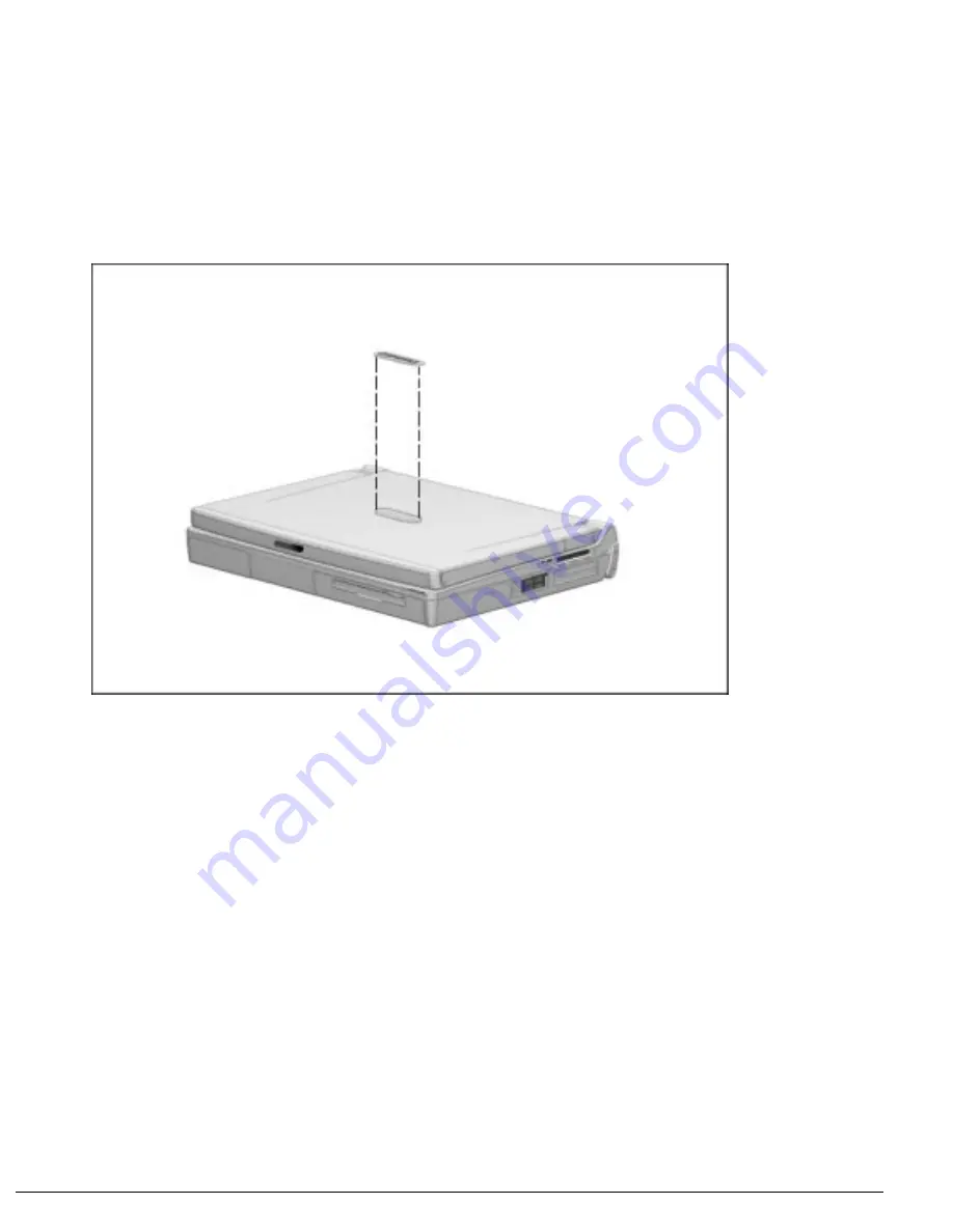
The computer logo has an adhesive backing for installation. Remove the protective
covering from the adhesive back and install the logo (Figure 5-7). The logo is upside
down when viewed from the back of the computer with the display open.

Figure 5-7.

  Installing the Computer Logo

Содержание Armada 7800 6266 T 5000 D 0 1

Страница 1: ...r Corporation All rights reserved Printed in the U K COMPAQ ARMADA and LTE are registered in the U S Patent and Trademark Office Microsoft MS DOS and Windows are registered trademarks of Microsoft Corporation The software described in this guide is furnished under a license agreement or nondisclosure agreement The software may be used or copied only in accordance with the terms of the agreement Pr...

Страница 2: ... in the caution could result in damage to equipment or loss of information IMPORTANT Text set off in this manner presents clarifying information or specific instructions NOTE Text set off in this manner presents commentary sidelights or interesting points of information Technician Notes WARNING Only authorized technicians trained by Compaq should repair this equipment All troubleshooting and repai...

Страница 3: ...rosoft Windows 95 Windows NT 4 0 User s Guide n Compaq Service Training Guides n Compaq Service Advisories and Bulletins n Compaq QuickFind n Compaq Service Quick Reference Guide n Compaq Armada 7800 Family of Personal Computers Maintenance and Service Guide n Compaq Armada 7800 Family of Personal Computers Illustrated Parts Map n Compaq ArmadaStation and Armada MiniStation E and EX Maintenance an...

Страница 4: ...quipment Options 1 11 1 3 Computer External Components 1 12 1 4 Design Overview 1 19 System Board 1 19 Chapter 2 TROUBLESHOOTING 2 1 Preliminary Steps 2 2 2 2 Clearing Passwords 2 3 2 3 Power On Self Test POST 2 4 2 4 POST Error Messages 2 4 2 5 Compaq Utilities 2 8 Computer Setup 2 8 Computer Checkup TEST 2 10 Running View System Information INSPECT 2 17 Running Compaq Diagnostics 2 18 Boot Seque...

Страница 5: ...equired 4 1 4 2 Service Considerations 4 1 Plastic Parts 4 1 Cables and Connectors 4 2 4 3 Preventing Damage to Removable Drives 4 2 4 4 Preventing Electrostatic Damage 4 3 Packaging and Transporting Precautions 4 3 Workstation Precautions 4 4 Grounding Equipment and Methods 4 5 Electrostatic Voltage Levels and Protective Materials 4 6 Chapter 5 REMOVAL AND REPLACEMENT PROCEDURES 5 1 Serial Number...

Страница 6: ...y Devices 5 24 Inserting MultiBay Devices 5 27 5 10 MemoryExpansion 5 28 Removing the Memory Expansion Slot Cover 5 28 Removing a Memory Expansion Board 5 30 Inserting a Memory Expansion Board 5 31 Replacing the Memory Expansion Slot Cover 5 32 5 11 Keyboard Assembly 5 33 5 12 Power Supply 5 36 5 13 Fan Assembly 5 38 5 14 Audio USB Board 5 39 5 15 Modem Board 5 40 5 16 Audio Assembly Bracket 5 42 ...

Страница 7: ... 3 6 4 Diskette Drive Specifications 6 4 6 5 CD ROM Drive Specifications 6 5 6 6 Battery Pack Specifications 6 6 6 7 System Interrupts 6 7 6 8 System DMA 6 8 6 9 System I O Addresses 6 9 6 10 System Memory Map 6 11 6 11 Modem Chipset Specifications 6 11 Appendix A CONNECTOR PIN ASSIGNMENTS A 1 Appendix B POWER CORD SET REQUIREMENTS B 1 Appendix C SCREW MATRIX C 1 Index I 1 ...

Страница 8: ...nsive multimedia support The computer provides desktop functionality and connectivity through the optional ArmadaStation and Armada MiniStation Figure 1 1 Compaq Armada 7800 Personal Computer Features The computer has the following standard features Intel 266 MHz Pentium II processor with 64 bit architecture MMX technology and 512 KB level 2 cache memory Industry leading portable computer AGP impl...

Страница 9: ...ps standard for wireless file transfer printing and file synchronization Built in stereo speakers providing Compaq PremierSound microphone and jacks for stereo audio sound with electronic equalization and wave table synthesis Energy Star compliant power saving features Ports and connectors for external equipment including universal serial bus USB serial parallel external monitor and PS 2 compatibl...

Страница 10: ...ada 7800 6266 T 5000 D 0 3 64 MB RAM standard Armada 7800 7 8 0 0 6 266 T 5000 D M 1 Key A B C D E F G H I Key Description Options A Line designator 7 Performance B Family designator 8 Armada 7800 C Processor type 6 Intel Pentium II processor with MMX technology D Processor speed 266 266 MHz processor E Panel type T 13 3 inch XGA TFT 1024 768 F Hard drive capacity 5000 5 0 GB G Drive type D 20X Ma...

Страница 11: ... Manageability Help Asset Management AssetControl retrieves component information when on the road or connected to the network AssetControl also enables the network administrator to remotely retrieve information from any Compaq computer connected to the network The information can be used to assist in tracking and maintaining the computer and its components It provides the following information In...

Страница 12: ...g problems and battery pack failure Monitor alert diagnoses and displays external monitor operational problems Memory alert reports memory board configuration changes when a memory board is removed added or reconfigured It also provides the previous and current configurations for comparison The alerts work with or without network connection Of course if the computer is not connected to the network...

Страница 13: ...optimizes software upgrade and customer support procedures Compaq provides support software to optimize the performance of the computer This support software is accessible through a monthly subscription CD ROM Support software can also be downloaded from the Compaq web site at http www compaq com Support software includes Locator browser searches for the latest device drivers utilities ROM images ...

Страница 14: ...ips with Computer Available as Option Battery pack Modem not available in all locations Modem cable country specific Diskette drive MultiBay weight saver Slip case shipped with computer only in Europe Middle East and Africa EasyPoint III caps Telephone cable country specific Power cable 3 prong to 2 prong converter Japan only Quck Restore CD ROM Security kit ArmadaStation Armada MiniStation E and ...

Страница 15: ...mper resistant security screw included with the computer can be used to provide added security The security wrench also included with the computer must be used to remove the tamper resistant security screw System memory can be upgraded as shown in Table 1 3 Table 1 3 Memory Upgrade Base Memory on System Board Memory Expansion Board Total Memory 32 MB 16 MB 1 16 MB 48 MB 32 MB 32 MB 2 16 MB or 1 32...

Страница 16: ...that fits into the computer ArmadaStation or Armada MiniStation EX MultiBays The diskette drive is a three mode type that is compatible with 1 44 Megabytes 1 2 Megabytes and 720 Kilobytes formatted AT drive types The system supports a maximum of two diskette drives one in the computer MultiBay and one in the ArmadaStation or Armada MiniStation EX MultiBay Hard Drive The dedicated hard drive bay su...

Страница 17: ...supports 3 5 inch and 5 25 inch media in the following formats ISO 9660 the most common CD ROM format CD ROM XA eXtended Architecture a standard for storing multimedia information Photo CD single and multisession Kodak s format for storing photographic images on CD ROM CD i and CD i Bridge CD DA digital audio CD ROM Mode 1 and Mode 2 CD I Mode 2 Form 1 and Form 2 Video CD ...

Страница 18: ...te from a 12 volt aircraft DC socket and from an automobile cigarette lighter receptacle Lithium Ion Battery Pack The battery pack can be used in the computer dedicated battery bay computer MultiBay ArmadaStation MultiBays and Armada MiniStation EX MultiBay and battery charging bay Battery Charger The external Battery Charger has the following features Two battery charging bays Charging of one bat...

Страница 19: ...tch Opens the computer 2 Mono Microphone Allows for audio input located on the inside and outside of the display can be used whether the computer is open or closed 3 Stereo speakers 2 Produce high quality stereo sound 4 Tilt feet 2 Tilt the computer for ease of use 5 Fan Provides airflow exhaust 6 Battery bay Accepts Lithium ion battery pack 7 Hard drive bay Accepts removable hard drive 8 MultiBay...

Страница 20: ...m Component Function 1 Security slot Secures the computer to a fixed object to prevent theft 2 PC Card eject levers 2 Eject PC Cards from the slots 3 PC Card slots Accepts 16 and 32 bit CardBus PC Cards 4 25 pin modem connector Connects a country specific 25 pin telephone cable all countries except North America Latin America Japan China and Hong Kong Also connects a cellular phone to the computer...

Страница 21: ...ve powered or unpowered hubs can be connected in any sequence as long as two unpowered hubs are not connected next to each other When running a lower version of Windows or Windows NT or if using a different operating system up to two hubs can be connected 2 Mono microphone jack Connects mono microphone disabling the built in microphone 3 Stereo speaker headphone jack Connects external stereo speak...

Страница 22: ...al connector Connects optional serial devices such as a mouse 9 Parallel connector Connects optional parallel devices such as a printer 10 Docking connector Connects optional ArmadaStation or Armada MiniStation E or EX 11 Keyboard mouse connector Connects an optional full sized keyboard or a mouse Both external mouse and computer pointing device are active An optional splitter adapter allows both ...

Страница 23: ...trol Adjusts volume of stereo speakers 5 Power switch Turns computer on or off 6 Scroll lock key Turns on the scroll function 7 Page up and page down keys Moves image to previous or following screen 8 Num Lk key Turns on the numeric lock function 9 Embedded numeric keypad Converts keys to numeric keypad 10 Cursor control keys Moves the cursor around the screen 11 Fn key Used with hotkeys to perfor...

Страница 24: ...s reached Blinks continuously if critical low battery condition is reached If AC power is not connected within 20 seconds Hibernation is initiated unless Hibernation has been disabled 3 Hard drive light green Turns on when the hard drive is being accessed 4 MultiBay drive light green Turns on when the MultiBay device is being accessed or when a battery pack in the MultiBay is charging or waiting t...

Страница 25: ... hard drive bay 3 Docking restraint latch recess Secures the computer to the ArmadaStation 4 Hard drive MultiBay security screw slot Allows hard drives and MultiBay devices to be secured inside the computer using the single and dual bay security screws 5 MultiBay release latch Releases devices from the MultiBay 6 Memory expansion slot cover Covers the memory expansion compartment 7 Labels area Con...

Страница 26: ...with a 3 1 volt Intel Mobile Pentium II 266 MHz processor For ventilation an electrical fan is installed The fan operates on from 5 to 12 volts and is controlled by a temperature sensor The fan is designed to turn on automatically when high temperature conditions exist These conditions are affected by high external temperatures system power consumption power management battery conservation configu...

Страница 27: ...problem is resolved and the error message does not return When the problem is resolved stop performing the troubleshooting steps and do not complete the remaining recommended actions Refer to Chapter 5 for removal and replacement procedures that are recommended If the problem is intermittent check the computer several times to verify that the problem is solved The following table describes the tro...

Страница 28: ... not want to test If you want to use the printer to log error messages leave it connected to the computer NOTE If a problem only occurs when an external device is connected to the computer the problem could be with the external device or its cable Isolate the problem by running POST with and without the external device connected 9 Use Compaq Utilities and loopback plugs in the serial and parallel ...

Страница 29: ...mbly bracket Section 5 16 8 Remove the lithium disc cell battery Section 5 17 9 Disconnect the auxiliary battery Section 5 19 10 Allow the computer to set for five minutes 11 Reconnect the auxiliary battery 12 Install the lithium disc cell battery 13 Install the audio assembly bracket modem board audio USB board and keyboard 14 Reconnect the power cord Do not reinstall the battery pack yet 15 Turn...

Страница 30: ...play is not functioning well enough to show POST error messages refer to the Troubleshooting tables in Section 2 7 If POST detects an error one of the following events occurs A message with the prefix WARNING appears informing you where the error occurred The system pauses until you press F1 to continue A message with the prefix FATAL appears informing you where the error occurred After the messag...

Страница 31: ...eplace the diskette drive Hard disk controller error The hard drive controller failed to respond to the reset command Check the drive parameters Turn off the system and check all related connections Keyboard controller failure The keyboard failed the self test command Replace the system board Keyboard failure The keyboard failed to respond to the RESET ID command Replace the keyboard If the proble...

Страница 32: ...unt and transfer address registers within the primary and secondary DMA controllers failed 4 Faulty DMA page registers A walking bit read write of the 16 DMA controller page registers starting at location 80 Hex failed 0 Faulty refresh circuits A continuous read write test of port 61h found that bit 4 Refresh Detect failed to toggle within an allotted amount of time 1 Interrupt controller failed A...

Страница 33: ...ulty 2 S S S P S L L P The ROM checksum is incorrect 3 S S S P L S S P The CMOS RAM test failed 4 S S S P L S L P The DMA controller is faulty 5 S S S P L L S P The interrupt controller failed 6 S S S P L L L P The keyboard controller failed 7 S S L P S S S P Graphics adapter is faulty 8 S S L P S S L P Internal RAM is faulty Replace memory board or system board if memory on system board is faulty...

Страница 34: ...allow you to set custom features such as security options power conservation levels and startup preferences If you are running Windows 95 the computer automatically recognizes and configures the system for new devices If you have a configuration problem or want to view or reset configuration settings you can use Computer Setup NOTE If you are running Windows 95 you should use Computer Setup only t...

Страница 35: ...es Other miscellaneous devices Categories by connection System Features security power boot management System Devices keyboard mouse parallel and serial ports ISA ISA bus and connected devices PCI PCI bus and connected devices PC Card PC Card devices Running Computer Setup 1 Turn on or restart the computer by clicking Start Shut Down Restart the computer 2 Press F10 when the blinking cursor appear...

Страница 36: ...at Computer Checkup generates NOTE Compaq Utilities are intended for testing only Compaq supplied components Testing of non Compaq components may be inconclusive Running Computer Checkup TEST 1 Plug the computer into an external power source A low battery condition can interrupt the program 2 Connect a printer if you want to print a log of error messages 3 Turn on the external devices that you wan...

Страница 37: ...ter Checkup each time you complete a recommended action step If the problem is resolved when POST and Computer Checkup are rerun i e with no error codes do not perform the remaining recommended action steps NOTE The error codes in the following tables are listed in an AYY XX format where A or AA Number that represents the faulty assembly YY Test or action that failed XX Specific problem Table 2 4 ...

Страница 38: ...m address test failed Table 2 6 Keyboard Test Error Codes Error Code Description Recommended Action 300 xx Failed ID Test The following steps apply to error codes 300 xx through 304 xx 1 Reseat the keyboard assembly 301 xx Failed Self test Interface Test 2 Replace the keyboard and retest 302 xx Failed Individual Key Test 3 Replace the system board and retest 304 xx Failed Keyboard Repeat Test Tabl...

Страница 39: ... test failed 3 Replace the system board and retest 604 xx Diskette random read test failed 605 xx Diskette ID media test failed 606 xx Diskette speed test failed 609 xx Diskette reset controller test failed 610 xx Diskette change line test failed 697 xx Diskette type error 698 xx Diskette drive speed not within limits 699 xx Diskette drive media ID error 1 Replace media 2 Run Compaq Utilities Tabl...

Страница 40: ...ve and retest 1704 xx Hard drive random seek test failed 4 Replace the system board and retest 1705 xx Hard drive controller test failed 1706 xx Hard drive ready test failed 1707 xx Hard drive recalibration test failed 1708 xx Hard drive format bad track test failed 1709 xx Hard drive reset controller test failed 1710 xx Hard drive park head test failed 1715 xx Hard drive head select test failed 1...

Страница 41: ...llowing actions apply to error codes 2402 xx through 2456 xx 2403 xx Video attribute test failed 1 Run Compaq Utilities 2404 xx Video character set test failed 2 Disconnect external monitor and test with internal LCD display 2405 xx Video 80 25 mode 9 14 character cell test failed 3 Replace the display assembly and retest 4 Replace the system board and retest 2406 xx Video 80 25 mode 8 8 character...

Страница 42: ...display audio cable connection 3206 xx Audio System Internal Error Replace the audio board and retest Table 2 13 Pointing Device Interface Test Error Codes Error Code Description Recommended Action 8601 xx Pointing device test failed The following action applies to error codes 8601 xx and 8602 xx Replace the keyboard CPU cover assembly 8602 xx Interface test failed Table 2 14 CD ROM Test Error Cod...

Страница 43: ...n the cursor blinks in the upper right corner of the display 4 If prompted select a language 5 Click View System Information INSPECT 6 Click the item you want to view from the following list System Audio ROM Operating system Keyboard System files System ports Windows files System storage Miscellaneous Graphics Memory Network applicable only if computer is docked in the ArmadaStation or Armada Mini...

Страница 44: ... Click the System Features icon Boot Management box MultiBoot tab 3 Designate the hard drive boot startup sequence you want 4 Click OK to accept the changes Factory Default Settings Table 2 15 Initialization Enable POST Memory Test Checked enabled Keyboard Num Lock Unchecked Off 1 Hard drive in the computer hard drive bay 2 Hard drive in the computer MultiBay 3 Hard drive in the ArmadaStation or A...

Страница 45: ...Hibernation Timeout 1 hour Drive Timeout 6 minutes Screen Timeout 4 minutes Custom Suspend Time disabled Hibernation Timeout low battery Drive Timeout always on Screen Timeout always on Table 2 18 Security Enable QuickLock QuickBlank Unchecked Disabled Enable Power On Password Unchecked Disabled Disable Serial Infrared Ports Unchecked Enabled Disable Parallel Port Unchecked Enabled Disable PC Card...

Страница 46: ... application Checklist for Solving Problems If you encounter a minor problem with the computer or software applications go through the following checklist for possible solutions Is the computer connected to an external power source or does it have a fully charged battery pack installed Are all cables connected properly and securely Did the diskette drive contain a nonbootable diskette when you tur...

Страница 47: ...e computer volume control and or the software volume control needs to be adjusted In Windows 95 adjust the computer volume control buttons and adjust the volume control in Multimedia Properties NOTE The volume control in Multimedia Properties only affects the Wave audio sources such as system sounds and wav file playback To change other sources such as MIDI video sound and game effects use the Vol...

Страница 48: ...t the headphones or speakers to enable the internal speakers External microphone does not work The wrong type of microphone or microphone plug is being used Check to see if a monophonic electret condenser microphone with a 3 5 mm plug is being used The microphone may not be connected properly Ensure that the microphone plug is properly connected to the mono microphone jack Sound source is not sele...

Страница 49: ...the top right corner of the computer Use the volume control and mixing features available in Control Panel Multimedia Sound source not selected Verify that the sound source is selected in Control Panel Multimedia Volume or mixing controls set incorrectly Adjust the volume with the volume control buttons located at the top right corner of the computer Check the volume and mixer controls in Control ...

Страница 50: ...charged battery pack Check battery status by pushing the button on the battery pack Computer beeped five times and battery light is blinking Computer has entered a low battery condition Immediately save any open file s Then do one of the following Connect the computer to an external power source Turn the computer off and replace the battery pack Computer battery light blinks to indicate low batter...

Страница 51: ...ttery charge is low Connect the computer to an external source for approximately 24 hours to fully charge the auxiliary battery Auxiliary battery is at the end of its life Replace the auxiliary battery Battery pack charge does not last as long as expected Battery pack is being exposed to high temperatures or extremely cold temperatures Keep the battery pack within the recommended operating tempera...

Страница 52: ...CD loading tray is loaded upside down Open the CD loading tray turn over the compact disc label facing up then close the tray Compact disc has a scratch on its surface Insert a different compact disc CD ROM drive is not recognized by the computer CD ROM drive is not connected properly If you are running Windows 95 turn off the computer Remove the CD ROM drive from the MultiBay then reinsert it If ...

Страница 53: ...are using Windows NT format the diskette by entering format a at the system prompt Diskette drive cannot write to a diskette Diskette is not formatted Format the diskette If you are using Windows 95 1 From the Windows 95 desktop double click My Computer 2 Click 3 Floppy A File Format 3 Fill in the required information then click Start If you are using Windows NT format the diskette by entering for...

Страница 54: ...occurs Hard drive has bad sectors or has failed Do one of the following If you are running Windows 95 access ScanDisk by clicking Start Programs Accessories System Tools ScanDisk then check the Automatically fix errors box Click Start to begin scanning If you are running Windows NT go to the system prompt and type chkdsk to scan for errors Reformat the hard drive Contact your Compaq authorized dea...

Страница 55: ...ables are unplugged Ensure that all cables are properly and securely connected and the power cord is plugged into an electrical outlet Power switch of new external device is not turned on 1 Turn off the computer 2 Turn on the external device 3 Turn on the computer to integrate the device with the computer system New device is not configured for Windows NT Use Computer Setup to view settings for th...

Страница 56: ...ts and reassign as necessary Baud rate conflict Select the same baud rate for both computers bits conflict Select the same bits setting for both computers Stop bit conflict Select the same stop byte for both computers Parity conflict Select the same parity setting for both computers Data transmission problem Direct sunlight fluorescent light or flashing incandescent light is close to the infrared ...

Страница 57: ...abeled This location has call waiting Select 70 70 or 1170 from the drop down list to disable call waiting for your dialing area Noisy telephone line Phone line noise causing garbled or missing characters or slow data transfer speeds Check your telephone and modem cable connections If they are a little loose they can cause noise on the line Check with your local telephone company for a phone line ...

Страница 58: ...If the modem displays OK the modem and computer are working together If the modem displays ERROR or does not respond restart the computer and repeat step 1 3 Type ATDT and listen for a dial tone 4 Type ATH0 zero to hang up Speaker Control AT Command ATM is set to 0 Set the Speaker Control to 1 1 Click Start Programs Accessories HyperTerminal 2 Go to Command Mode type ATM1 and press Enter 3 Type AT...

Страница 59: ... interferes with other telephony devices Germany Austria and Switzerland only The modem cable does not provide the additional 4 wire connection required in Germany Austria and Switzerland to form the serial pass through necessary so that other devices can work on the same phone line To use another telephony device on the same line in these countries unplug the modem cable from the wall jack first ...

Страница 60: ...cket Double click the Texas Instruments TI 1131 CardBus controller to view device properties Deselect the Disable in this hardware profile check box Card or card driver is not compatible with the computer or with the operating system Contact service provider for a list of compatible PC Cards Computer beeps twice but modem and or fax does not work Telephone cord is not plugged in all the way Verify...

Страница 61: ... point where Hibernation was initiated NOTE To change the Hibernation timeout setting in Windows 95 click the Hibernation tab in Power Properties In Windows NT run Computer Setup and select Power Management Computer turned off while it was left unattended and will not turn on System initiated Hibernation and or shut down because of a critical low battery condition Replace the battery pack with a f...

Страница 62: ...reen save was initiated after the Power Management timeout period Press any key or click the mouse Brightness or contrast needs adjusting Adjust the control s with the hotkeys Fn F9 and Fn F10 Screen has overheated If computer is in direct sunlight move it and allow it to cool Computer screen is blank and the screen on an external monitor displays information Display was switched to the external m...

Страница 63: ...isplay device drivers are installed or incorrect resolution is set Double click the Display icon in Control Panel click the Settings tab and set the correct display type and resolution for the external monitor The external monitor is not Energy Star compliant but monitor energy saving feature is enabled Complete these steps 1 Press any key or move the pointing device to restore the display 2 If di...

Страница 64: ...nd tier External device connected to a USB connector does not work during startup before Windows 95 loads During startup only two tiers are supported by the USB connector These tiers can include no more than two hubs on the first tier and no more than one keyboard and one pointing device on the first or second tier Use the external device only after Windows 95 has loaded Reduce the number of conne...

Страница 65: ...e identical to corresponding spare parts on the Armada 7800 computer However due to color and mechanical differences Armada 7700 spare parts should never be used when servicing an Armada 7800 computer CAUTION Only spare parts listed in this chapter should be used to service an Armada 7800 computer Failure to follow this caution can cause damage to the computer ...

Страница 66: ...omponents Figure 3 1 Computer System Major Components Table 3 1 Spare Parts Computer System Major Components Item Description Spare Part Number 1 Display assembly includes logo kit audio assembly bracket thermal pad and keyboard label kit 315015 001 continued ...

Страница 67: ...embly ground clips 2 Keyboard label kit Audio assembly bracket thermal pad Keyboard thermal pad base feet keyboard connector insulator 9 Modem board includes insulator and keyboard label kit U S model International model 313906 001 313906 002 Japanese model 313906 291 Audio only board includes RJ 11 cover plug and keyboard label kit 314956 001 10 System board includes not illustrated 314937 001 Ex...

Страница 68: ... Kit Components Table 3 2 Miscellaneous Plastics Kit Components Spare Part Number 313916 001 Item Description 1 Hard drive tray 2 Auxiliary battery retainer 3 Memory expansion slot cover 4 Left right rear covers 5 Top bottom PC Card eject levers Not Illustrated RJ 11 cover DAA cover plug Keyboard label kit ...

Страница 69: ...Figure 3 3 Miscellaneous Hardware Kit Components Table 3 3 Miscellaneous Hardware Kit Components Spare Part Number 314959 001 Item Description 1 Audio assembly bracket 2 Expansion connector shield 3 Processor module assembly ground clips 2 Keyboard label kit not illustrated ...

Страница 70: ... 001 2 Auxiliary battery 220807 001 3 Battery charger 277734 001 4 Automobile aircraft adapter Automobile aircraft adapter cable 313919 001 315083 001 5 Power cord Australian Danish European Italian Japanese 314957 011 314957 081 314957 002 314957 061 314957 291 Korean French German Swiss U K English Asia Pacific Hong Kong U S English 314957 AD1 314957 111 314957 031 314957 001 ...

Страница 71: ...standard equipment also available as option 305897 001 2 20X Max CD ROM drive standard equipment also available as option 314936 001 3 Diskette drive 1 44 megabyte 3 5 inch standard equipment 314941 001 4 External diskette drive available only as an option External diskette drive cable not illustrated 290837 001 258575 002 5 SuperDisc LS 120 drive available only as an option 327456 002 ...

Страница 72: ... 3 8 Illustrated Parts Catalog 3 6 Items that Ship with the Computer Figure 3 6 Items that Ship with the Computer ...

Страница 73: ... European Italian Japanese Korean French German Swiss U K English Asia Pacific Hong Kong U S English 314957 011 314957 081 314957 002 314957 061 314957 291 314957 AD1 314957 111 314957 031 314957 001 7 Auxiliary battery 220807 001 8 Telephone cable country specific 138609 001 9 Modem cable country specific 248080 001 10 Slipcase Europe Middle East Africa only 315108 001 11a 11b 11c 11d Security ki...

Страница 74: ... 3 10 Illustrated Parts Catalog 3 7 Options Figure 3 7 Options ...

Страница 75: ...5 001 212031 001 212030 001 212034 001 212033 001 185272 001 185268 001 185267 001 185271 001 185270 001 6 5 0 GB hard drive includes hard drive carrying case 305897 001 297189 B25 7 Headset 273139 001 220460 001 8 Battery charger 277734 001 220461 001 9 Battery pack Li ion 314939 001 220463 B25 10a 10b 10c 10d 10e 10f SpeedPaq Cellular PC Card Kit includes SpeedPaq Cellular PC Card computer inter...

Страница 76: ...it includes case utility tool connector removal tool loop back plugs 100767 001 3 9 Documentation Table 3 9 Spare Parts Documentation not illustrated Description Spare Part Number Armada 7800 Maintenance Service Guide 314960 001 Armada 7800 Illustrated Parts Map 314961 001 ArmadaStation and Armada MiniStation Maintenance Service Guide 296390 001 ArmadaStation and Armada MiniStation Illustrated Par...

Страница 77: ...ompartment cover screws and or tamper resistant hard drive security plate have been installed Tool kit includes connector removal tool loopback plugs and case utility tool X acto knife or scraper to remove thermal pad residue from audio assembly bracket and processor module assembly Refer to Section 5 15 4 2 Service Considerations Listed below are some of the considerations that you should keep in...

Страница 78: ...in Hibernation turn the computer on then shut it down Before removing a diskette drive or CD ROM drive ensure that a diskette or disc is not in the drive Ensure that the CD ROM tray is closed Before handling a drive ensure that you are discharged of static electricity While handling a drive avoid touching the connector Handle drives on surfaces that have at least one inch of shock proof foam Avoid...

Страница 79: ... its life expectancy Packaging and Transporting Precautions Use the following grounding precautions when packaging and transporting equipment To avoid hand contact transport products in static safe containers such as tubes bags or boxes Protect all electrostatic sensitive parts and assemblies with conductive or approved containers or packaging Keep electrostatic sensitive parts in their containers...

Страница 80: ...ce tools such as cutters screwdrivers and vacuums that are conductive When using fixtures that must directly contact dissipative surfaces use fixtures made of static safe materials only Keep work area free of nonconductive materials such as ordinary plastic assembly aids and Styrofoam Handle electrostatic sensitive components parts and assemblies by the case or PCM laminate Handle them only at sta...

Страница 81: ...d at standing workstations and are compatible with most types of shoes or boots On conductive floors or dissipative floor mats use them on both feet with a minimum of one megohm resistance between the operator and ground To be effective the conductive strips must be worn in contact with the skin Other grounding equipment recommended for use in preventing electrostatic damage include Antistatic tap...

Страница 82: ...r 6 000 V 800 V 400 V Removing DIPS from plastic tube 2 000 V 700 V 400 V Removing DIPS from vinyl tray 11 500 V 4 000 V 2 000 V Removing DIPS from Styrofoam 14 500 V 5 000 V 3 500 V Removing bubble pack from PCB 26 500 V 20 000 V 7 000 V Packing PCBs in foam lined box 21 000 V 11 000 V 5 000 V NOTE 700 volts can degrade a product Table 4 2 lists the shielding protection provided by antistatic bag...

Страница 83: ...l and Replacement Procedures 5 1 Serial Number The computer serial number should be reported to Compaq when requesting information or ordering spare parts The serial number is located on the bottom of the computer Figure 5 1 Figure 5 1 Serial Number Location ...

Страница 84: ...rive Bay Inserting a Hard Drive into the Hard Drive Bay Inserting a Hard Drive into the MultiBay Removing a Hard Drive from the MultiBay 5 9 MultiBay Devices Removing Drives from the MultiBay Inserting Drives into the MultiBay 5 10 Memory Expansion Removing the Memory Expansion Slot Cover Removing a Memory Expansion Board Installing a Memory Expansion Board Removing the Memory Expansion Slot Cover...

Страница 85: ... removed since it is on the same level on the chart as the fan Undock the computer Section 5 4 Disconnect computer Section 5 4 Remove battery pack Section 5 7 Remove memory Section 5 10 Remove the keyboard Section 5 11 Remove audio USB board Section 5 14 Remove modem Section 5 15 Remove audio assembly bracket Section 5 16 Remove Lithium disc cell battery Section 5 17 Remove processor module assemb...

Страница 86: ...ultiBay Section 5 7 4 Remove PC Cards Undocking the Computer If the computer is not docked in an ArmadaStation or Armada MiniStation go to the Disconnecting the Computer section If the computer is docked go to the Undocking the Computer from the ArmadaStation or Undocking the Computer from the Armada MiniStation section Undocking the Computer from the ArmadaStation 1 Unlock the ArmadaStation keylo...

Страница 87: ...rocedures 5 5 4 Press the eject button 1 The computer separates from the docking connector on the ArmadaStation 2 Figure 5 4 Figure 5 4 Undocking the Computer from the ArmadaStation 6 Slide the computer out of the ArmadaStation ...

Страница 88: ...n the computer 2 Close the computer 3 Lift the docking lever and slide it forward 1 The computer separates from the docking connector on the Armada MiniStation 2 Figure 5 5 Figure 5 5 Undocking the Computer from the Armada MiniStation 4 Slide the computer away from the Armada MiniStation and remove it ...

Страница 89: ...t docked in an ArmadaStation or Armada MiniStation refer to Figure 5 6 and follow these steps to disconnect the computer 1 Shut down the computer 2 Close the computer 3 Position the computer so the rear panel faces forward 4 Disconnect the power cord from the wall outlet 1 5 Disconnect the power cord from the computer 2 Figure 5 6 Disconnecting the Computer 7 Turn off and disconnect external devic...

Страница 90: ...mputer logo has an adhesive backing for installation Remove the protective covering from the adhesive back and install the logo Figure 5 7 The logo is upside down when viewed from the back of the computer with the display open Figure 5 7 Installing the Computer Logo ...

Страница 91: ...long adhesive backed rubber pads The computer feet are included in the Miscellaneous Hardware Spare Kit Install the feet by removing the protective covering from the adhesive back and attaching the feet to the bottom of the computer Figure 5 8 Figure 5 8 Installing the Computer Feet ...

Страница 92: ... the battery pack Removing a Battery Pack from the Battery Bay Follow these steps to remove a battery pack from the battery bay 1 If the computer is turned on press the suspend button If there is hard drive or diskette drive activity Suspend may not occur immediately The computer screen clears and the power suspend light begins to flash when Suspend is initiated If the computer is turned off or in...

Страница 93: ...he computer at an angle 1 so the bottom of the computer is accessible Figure 5 9 3 Slide the battery release latch to the right 2 4 Grasp battery pack using the recess 3 beneath the battery bay Figure 5 9 Releasing a Battery Pack from the Battery Bay ...

Страница 94: ... a Battery Pack from the Battery Bay Removing a Battery Pack from the MultiBay 1 If the computer is turned on press the suspend button If there is hard drive or diskette drive activity Suspend may not occur immediately The computer screen clears and the power suspend light begins to flash when Suspend has been initiated ...

Страница 95: ...ttery pack has been secured in the MultiBay with a single or dual bay security screw 2 remove the screw with the security wrench included with the computer 4 Slide the MultiBay release latch toward the rear of the computer 3 5 Grasp the battery pack using the recess 4 beneath the MultiBay Figure 5 11 Releasing a Battery Pack from the MultiBay ...

Страница 96: ... 5 14 Removal and Replacement Procedures 6 Pull the battery pack out of the MultiBay Figure 5 12 Figure 5 12 Removing a Battery Pack from the MultiBay ...

Страница 97: ...he battery bay until the computer is fully reassembled 1 With the battery pack label facing up and the battery pack contacts facing the computer slide the battery pack into the battery bay until it clicks into place Figure 5 13 Figure 5 13 Inserting a Battery Pack into the Battery Bay 2 If the computer is in Suspend press the suspend button to return to your work ...

Страница 98: ...1 With the battery pack label facing up and the battery pack contacts facing the computer slide the battery pack into the MultiBay until it clicks into place 2 If the battery pack was secured in the MultiBay using a single or dual bay security screw replace the screw Figure 5 14 Figure 5 14 Inserting a Battery Pack into the MultiBay 3 If the computer is in Suspend press the suspend button to retur...

Страница 99: ... 2 Tilt the computer at an angle 1 so the bottom of the computer is accessible Figure 5 15 3 If the hard drive has been secured in the hard drive bay with a single or dual bay security screw 2 remove the screw with the security wrench included with the computer 4 Slide the hard drive release latch to the left 3 5 Grasp the hard drive using the recess beneath the hard drive bay 4 Figure 5 15 Releas...

Страница 100: ... 5 18 Removal and Replacement Procedures 6 Pull the hard drive out of the hard drive bay Figure 5 16 Figure 5 16 Removing a Hard Drive from the Hard Drive Bay ...

Страница 101: ...he metal hard drive up and out of the plastic hard drive tray Figure 5 17 Figure 5 17 Removing the Hard Drive from the Hard Drive Tray 8 If you are not inserting another hard drive insert the hard drive tray into the hard drive bay until it is seated ...

Страница 102: ... drive bay by sliding the hard drive release latch to the left 3 Grasp the hard drive tray using the recess beneath the hard drive bay 4 Pull the hard drive tray out of the hard drive bay 5 Insert the metal hard drive into the plastic hard drive tray with the connectors protruding through the opening in the rear of the tray Figure 5 18 Figure 5 18 Inserting a Hard Drive into the Hard Drive Tray ...

Страница 103: ... 6 Slide the hard drive assembly into the hard drive bay Figure 5 19 Figure 5 19 Inserting a Hard Drive into the Hard Drive Bay 7 If the hard drive was secured in the hard drive bay using a single or dual bay security screw replace the screw ...

Страница 104: ...t a hard drive into the MultiBay This adapter is included with the purchase of an optional hard drive 1 Save all work exit all applications and shut down the computer 2 Push back the slide tab 1 on the Armada 7000 Hard Drive MultiBay Adapter Figure 5 20 3 Lower the hard drive 2 into the adapter 4 Slide the hard drive toward the connector 3 in the adapter until the connectors are seated Figure 5 20...

Страница 105: ...ll applications and shut down the computer 2 Tilt the computer at an angle 1 so the bottom of the computer is accessible Figure 5 21 3 If the hard drive assembly is secured in the MultiBay with a single or dual bay security screw 2 remove the screw with the security wrench included with the computer 4 Slide the MultiBay release latch 3 toward the rear of the computer 5 Grasp the hard drive assembl...

Страница 106: ...om the MultiBay If you are not inserting another drive or a battery pack into the MultiBay insert the MultiBay weight saver included with the computer 5 9 MultiBay Devices Removing MultiBay Devices 1 Save all work exit all applications and shut down the computer 2 Remove the media diskettes CD ROMs etc from the drive Ensure that the CD tray is closed ...

Страница 107: ... If the drive has been secured in the MultiBay with a single or dual bay security screw 2 remove the screw with the security wrench included with the computer 5 Slide the MultiBay release latch 3 toward the back of the computer 6 Grasp the drive using the recess 4 beneath the MultiBay Figure 5 23 Releasing a Drive from the MultiBay ...

Страница 108: ...dures 7 Pull the drive out of the MultiBay Figure 5 24 Figure 5 24 Removing a Drive from the MultiBay If you are not inserting another drive or a battery pack into the MultiBay insert the MultiBay weight saver included with the computer ...

Страница 109: ...tions and turn off the computer 2 Remove the media diskettes CD ROM s etc from the drive to be inserted in the MultiBay Ensure that the CD tray is closed 3 With the bezel facing out slide the drive into the MultiBay until it clicks into place Figure 5 25 Figure 5 25 Inserting a Drive into the MultiBay ...

Страница 110: ...ents Before beginning this procedure ensure that you are properly grounded For more information refer to Appendix C Electrostatic Discharge 1 Prepare the computer for disassembly Section 5 4 2 Remove any battery pack s from the computer Section 5 7 WARNING Failure to unplug the power cord and remove the battery pack before installing a memory expansion board can damage the equipment and expose you...

Страница 111: ...hat secures the memory expansion slot cover to the computer 1 Figure 5 26 A security wrench is needed to remove the screw securing the cover 5 Slide the cover to the right 2 and lift it straight up to remove it Figure 5 26 Removing the Memory Expansion Slot Cover ...

Страница 112: ...3 Lift up the edge of the memory expansion board 2 4 Pull the memory expansion board out of the memory expansion slot at a 45 degree angle 3 Figure 5 27 Removing a Memory Expansion Board 5 Place the memory expansion board in an electrostatic safe container 6 If no memory expansion board is to be installed reset the memory insulator 7 Replace the memory expansion slot cover and install the screw ...

Страница 113: ...orrect positioning 1 Insert the memory expansion board into an empty memory expansion slot at a 45 degree angle 1 Figure 5 28 2 Push the board into place until it is seated 3 Push the memory expansion board down until the board is seated in the plastic retention clips 2 Figure 5 28 inserting a Memory Expansion Board 4 Run Computer Setup Section 2 5 ...

Страница 114: ...ator are tucked inside the memory expansion compartment Figure 5 29 2 Replace the memory expansion slot cover 2 by placing it flush over the memory expansion compartment then sliding it left until it is seated 3 Secure the memory expansion slot cover to the computer with a memory expansion slot cover security screw 3 or a standard Torx T 10 screw Figure 5 29 Replacing the Memory Expansion Slot Cov...

Страница 115: ...Remove any battery pack s from the computer Section 5 7 3 Turn the computer upside down with the rear panel facing forward 4 Remove the nine screws from the bottom of the computer Figure 5 30 CAUTION The two screws removed from the highlighted screw holes are shorter than the other seven screws Make sure these shorter screws are installed in the same locations when replacing the keyboard assembly ...

Страница 116: ...will open NOTE With the display open and the battery pack and hard drive removed the weight of the display makes the computer susceptible to being easily tipped over 7 Peel off the keyboard warning label from the keyboard and remove the two screws securing the keyboard to the computer Figure 5 31 Figure 5 31 Removing the Keyboard Warning Label and Screws ...

Страница 117: ...yboard assembly IMPORTANT A set of keyboard warning labels is included with each keyboard assembly spare part kit and various other spare part kits and spare parts that require removal of the keyboard assembly Select a language from the set and place the label in the upper right corner of the keyboard assembly This label contains a warning message to prevent physical discomfort and harm This label...

Страница 118: ...er and lifting it off the power supply Figure 5 33 5 Use the connector removal tool to disconnect the power supply cable 2 from the system board 6 Remove the two screws that secure the power supply to the system board and the screw that secures the ground clip to the processor module assembly 3 Make sure the ferrite beads on the power supply cable do not obstruct the removal of the inboard screw N...

Страница 119: ...n the front of the power supply 2 and swing it up and away until it clears the computer Figure 5 34 Removing the Power Supply Reverse the above procedure to install the power supply CAUTION Make sure the fan cable is not pinched when installing the power supply Also make sure the power supply cable Is tucked away from the battery connector and battery charging bay Failure to follow these cautions ...

Страница 120: ... Figure 5 35 5 Release the fan assembly from the brackets 2 that secure either side of the assembly by pulling the brackets apart 6 Lift the fan assembly out of the computer 3 Figure 5 35 Removing the Fan Assembly Reverse the above procedure to install the fan assembly When installing it make sure the alignment tabs on the sides of the rubber mounting sleeve slide into the slots on the fan mountin...

Страница 121: ... The keyboard assembly must be removed to access the audio USB board 1 Prepare the computer for disassembly Section 5 4 2 Remove all battery packs Section 5 7 3 Remove the keyboard assembly Section 5 11 4 Position the computer so the rear panel faces forward 5 Remove the two screws on either side of the USB connector Figure 5 36 Figure 5 36 Removing the Audio USB Board Screws ...

Страница 122: ...ard insulator 3 Figure 5 37 Removing the Audio USB Board Reverse the above procedure to install the audio USB board 5 15 Modem Board The modem board is located in the right rear area of the computer and connects to the audio USB and system boards The keyboard assembly and audio USB board must be removed to access the modem board NOTE Computers not equipped with a modem contain an audio only board ...

Страница 123: ...erial on the connector and lift the connector straight up Failure to follow this caution can result in damage to the cable and connector on the modem audio only board 6 Remove the screw 2 that secures the modem board to the audio assembly bracket 7 Lift up on the left side of the modem board until the connection to the system board disconnects Lift the modem board out of the computer 3 Figure 5 38...

Страница 124: ...5 Remove the modem board Section 5 15 6 Remove the three screws 1 that secure the audio assembly bracket to the system board and the screw 2 that secures the audio assembly bracket to the processor module assembly Figure 5 39 7 Lift the audio assembly bracket out of the computer Firm pressure is required to remove it as it is attached to the processor module assembly by a thermal pad CAUTION To av...

Страница 125: ... audio assembly bracket 2 and the top of the heat sink on the processor module assembly 3 Figure 5 40 Scrape any residue from both components Install a new thermal pad on the processor module assembly 3 before replacing the audio assembly bracket A new thermal pad is spared with the processor module assembly and in the Miscellaneous Hardware Kit Figure 5 40 Location of Thermal Pad on the Processor...

Страница 126: ... assembly bracket make sure the auxiliary battery cable is routed between the modem connector 1 and the audio assembly bracket 2 Make sure the cable is not pinched by the screw standoff on the audio assembly bracket Figure 5 41 Figure 5 41 Routing the Auxiliary Battery Cable ...

Страница 127: ...4 2 Remove all battery packs Section 5 7 3 Remove the keyboard assembly Section 5 11 4 Remove the audio USB board Section 5 14 5 Remove the modem board Section 5 15 6 Remove the audio assembly bracket Section 5 16 7 Use the connector removal tool to push the left edge of the battery to the right and lift it out of the clip Figure 5 42 Figure 5 42 Removing the Lithium Disc Cell Battery Reverse the ...

Страница 128: ...h memory a heat sink a heat spreader and two ground clips The assembly attaches to the system board by two multipin connectors and two screws 1 Prepare the computer for disassembly Section 5 4 2 Remove all battery packs Section 5 7 3 Remove the keyboard assembly Section 5 11 4 Remove the audio USB board Section 5 14 5 Remove the modem board Section 5 15 6 Remove the audio assembly bracket Section ...

Страница 129: ... processor module assembly until the connection to the system board disconnects 2 Once disconnected lift up on the back of the processor module assembly to remove it IMPORTANT When removing and replacing the processor module assembly make sure the power supply cables are clear from the front left side of the assembly 3 Figure 5 43 Removing the Processor Module Assembly ...

Страница 130: ... ground clip when replacing the processor module assembly CAUTION The screws used to secure the ground clips to the processor module assembly are shorter than the screws used to secure the processor module assembly to the system board Do not interchange these screws Failure to follow this caution can result in damage to the computer Refer to Tables C 5 and C 6 in Appendix C Screw Matrix for part n...

Страница 131: ...bly Section 5 4 2 Remove all battery packs Section 5 7 3 Remove the keyboard assembly Section 5 11 4 Remove the audio USB board Section 5 14 5 Remove the modem board Section 5 15 6 Remove the audio assembly bracket Section 5 16 7 Remove the processor module assembly Section 5 18 8 Position the computer so the front faces forward ...

Страница 132: ... 5 50 Removal and Replacement Procedures 9 Remove the screw that secures the display video cable connector to the system board Figure 5 45 Figure 5 45 Removing the Display Video Cable Connector Screws ...

Страница 133: ...l and Replacement Procedures 5 51 10 Grasp the tabs on the display video connector 1 and disconnect the display video cable from the system board 2 Figure 5 46 Figure 5 46 Disconnecting the Display Video Cable ...

Страница 134: ... 5 52 Removal and Replacement Procedures 11 Disconnect the auxiliary battery cable from the system board Figure 5 47 Figure 5 47 Disconnecting the Auxiliary Battery Cable ...

Страница 135: ...uter 1 secure the display assembly to the computer The two screws in the middle 2 secure the display ground cable and auxiliary battery assembly to the computer NOTE The screws that secure the auxiliary battery assembly to the computer base assembly are shorter than the four screws that secure the display assembly to the base assembly Figure 5 48 Removing the Display Assembly and Auxiliary Battery...

Страница 136: ... 54 Removal and Replacement Procedures 14 Position the computer so the front faces forward 15 Lift the display assembly straight up from the computer Figure 5 49 Figure 5 49 Removing the Display Assembly ...

Страница 137: ...al and Replacement Procedures 5 55 16 Disconnect the auxiliary battery assembly from the display ground cable Figure 5 50 Figure 5 50 Disconnecting the Auxiliary Battery Assembly from the Display Ground Cable ...

Страница 138: ...he display ground cable The tabs on the ends of the ground cable 1 fit into the slots on the end of the auxiliary battery bracket 2 the pins on the bottom of the bracket 3 fit into the holes on the bottom of the ground cable 4 Figure 5 51 Figure 5 51 Attaching the Display Ground Cable to the Auxiliary Battery Assembly ...

Страница 139: ...al and Replacement Procedures 5 57 2 Position the display clutches so the display assembly is fully upright when it is installed in the computer Figure 5 52 Figure 5 52 Proper Position of the Display Clutches ...

Страница 140: ...y bracket on the hooks on the base assembly 3 Figure 5 53 Attaching the Display Ground Cable Auxiliary Battery Assembly to the Computer Base Assembly 5 Tilt the display assembly upright and position the display clutches in the proper locations in the base assembly 6 Position the computer so the rear panel faces forward 7 Install the two screws that secure the display ground cable and auxiliary bat...

Страница 141: ...onnect the display video cable 1 to the system board and install the screw 2 that secures the cable to the system board Figure 5 54 Figure 5 54 Connecting the Display Video Cable 10 Position the computer so the front of the computer faces forward ...

Страница 142: ... 11 Route the auxiliary battery cable between the modem connector 1 and the audio assembly bracket 2 Figure 5 55 12 Connect the auxiliary battery cable to the system board Figure 5 55 Connecting the Auxiliary Battery Cable to the System Board ...

Страница 143: ...Section 5 4 2 Remove all battery packs Section 5 7 3 Remove the keyboard assembly Section 5 11 4 Remove the audio USB board Section 5 14 5 Remove the modem board Section 5 15 6 Remove the audio assembly bracket Section 5 16 7 Pull out both PC Card eject levers 1 Figure 5 56 8 Lift the PC Card eject levers off their mounting post 2 Figure 5 56 Removing the PC Card Eject Levers ...

Страница 144: ...ition of each lever when installing the PC Card eject levers 1 Use a narrow flat tool such as a small flat blade screwdriver or a spoojer to hold back the PC Card eject buttons 1 Figure 5 57 2 Align the PC Card eject levers with the flush edges of each lever located on the inside 2 3 Place the PC Card eject levers on the mounting post 3 Figure 5 57 Installing the PC Card Eject Levers ...

Страница 145: ...eyboard assembly Section 5 11 4 Remove the power supply Section 5 12 5 Remove the fan assembly Section 5 13 6 Remove the audio USB board Section 5 14 7 Remove the modem board Section 5 15 8 Remove the audio assembly bracket Section 5 16 9 Remove the processor module assembly Section 5 18 10 Remove the display assembly Section 5 19 11 Remove the hard drive Section 5 8 12 Remove the MultiBay device ...

Страница 146: ... computer base assembly Figure 5 58 Figure 5 58 Removing the Expansion Connector Shield Reverse the above procedure to install the expansion connector shield CAUTION The connector shield must be present to prevent short circuits Failure to install the connector shield can result in damage to the computer ...

Страница 147: ... the new insulator and attach the new insulator to the back of the keyboard connector Figure 5 59 Removing the Keyboard Connector Insulator Reverse the above procedure to install the keyboard connector insulator CAUTION The keyboard connector insulator must be present to prevent short circuits Failure to install the keyboard connector insulator can result in damage to the computer 15 Remove the PC...

Страница 148: ...embly Figure 5 60 NOTE Two of the four screws removed in this step are flathead screws 2 When installing the system board these flathead screws must be installed in the front right section of the system board 17 Remove the standoff 3 that secures the system board to the computer base Figure 5 60 Removing the System Board Screws ...

Страница 149: ...e the system board and I O bracket to the CPU base assembly Figure 5 61 20 Remove the two 7 millimeter guide bushings 2 that secure the the system board and I O bracket to the CPU base assembly 21 Remove the screw located above the external keyboard mouse connector 3 Figure 5 61 Removing the System Board Screwlocks and Keyboard Mouse Connector Screw ...

Страница 150: ...tor from the base assembly Figure 5 62 Removing the System Board and Insulator Reverse the above procedure to install the system board and insulator IMPORTANT When installing the system board install and tighten the screwlock on the left side of the expansion connector first This aligns the system board to the I O bracket Next install and tighten the remaining screwlocks and screws This procedure ...

Страница 151: ... 11 4 Remove the power supply Section 5 12 5 Remove the fan assembly Section 5 13 6 Remove the audio USB board Section 5 14 7 Remove the modem board Section 5 15 8 Remove the audio assembly bracket Section 5 16 9 Remove the processor module assembly Section 5 18 10 Remove the display assembly Section 5 19 11 Remove the PC Card eject levers Section 5 20 12 Remove the system board Section 5 21 ...

Страница 152: ...14 Remove the two screws 1 that secure the PC Card assembly to the system board Figure 5 63 15 Lift the left side of the PC Card assembly to disconnect it from the system board 2 Figure 5 63 Removing the PC Card Assembly Reverse the above procedure to install the PC Card assembly ...

Страница 153: ...oard assembly Section 5 11 4 Remove the power supply Section 5 12 5 Remove the fan assembly Section 5 13 6 Remove the audio USB board Section 5 14 7 Remove the modem board Section 5 15 8 Remove the audio assembly bracket Section 5 16 9 Remove the processor module assembly Section 5 18 10 Remove the display assembly Section 5 19 11 Remove the PC Card eject levers Section 5 20 12 Remove the system b...

Страница 154: ...edures 14 Lift the back edge of the I O bracket When the bracket clears the computer base assembly lift it out of the base assembly Figure 5 64 Figure 5 64 Removing the I O Bracket Reverse the above procedure to install the I O bracket ...

Страница 155: ...Maximum Transient 90 240 VAC RMS 0 4 0 8 A RMS 47 to 63 Hz AC 1kV for 50 ns Automobile Adapter DC Input Requirements Operating Voltage Operating Power 10 to 24 VDC 30 to 40 W Temperature Operating Nonoperating 50 to 104 F 4 to 140 F 10 to 40 C 20 to 60 C Relative Humidity noncondensing Operating Nonoperating tw 38 7 C max 10 to 90 5 to 95 38 7 C Maximum Wet Bulb Altitude Operating Nonoperating 0 t...

Страница 156: ...Height Width Diagonal 7 98 in 10 64 in 13 30 in 20 28 cm 27 03 cm 33 79 cm Number of Colors 256 32K 64K 16M Contrast Ratio 150 1 Brightness 125 CD M2 Pixel Resolution Pitch Format Configuration 1024 768 RGB Stripe 0 264 0 264 mm Backlight Edge Lit bottom Character Display 80 25 Total Power Consumption 4 0 W ...

Страница 157: ... 1 Integrated Controller Yes Physical Configuration Cylinders Heads Bytes per Sector 6975 8 137 to 225 Logical Configuration Cylinders Heads Sectors per Track Bytes per Sector 10592 15 63 512 Buffer Size 512K Seek Times Typical including setting in ms Single Track Average Full Stroke 4 12 23 Transfer Rates Host Interface MB sec Media Mbits sec 16 6 60 2 to 98 5 ...

Страница 158: ...MB 1 2 MB 720 KB Light None Height 0 59 in 15 mm Bytes per Sector 512 Sectors per Track Hight Density Low Density 18 1 44 MB 15 1 2 MB 9 Tracks per Side High Density Low Density 80 1 44 MB 80 1 2 MB 80 Read Write Heads 2 Average Seek Times Track to Track high low Average high low Settling Time Latency Average 3 ms 95 ms 15 ms 100 ms ...

Страница 159: ... 15 mm Disc Diameter 12 cm 8 cm Disc Thickness 1 2 mm Track Pitch 1 6 µm Laser Divergence Output Power Type Wave Length 53 5 1 5 degrees 0 13 0 1 mw Semiconducter Laser GaA1As 780nm 25nm Access Time Random Full Stroke 150 ms 600 ms Audio Output Lever Line Out Headphone 0 7 V rms none Cache Buffer 256 KB Data Transfer Rate Sustained quad Sustained single Burst Startup Time 300 MB sec 150 KB sec 8 3...

Страница 160: ...8 80 cm Weight 0 89 lb 0 40 kg Energy Voltage Capacity 14 4 V 2 7 Ah Environmental Requirements Operating Temperatures Charging Temperatures Recommended Storage Temperatures No longer than 1 month No longer than 3 months No longer than 1 year 50 F to 104 F 50 F to 104 F 32 F to 140 F 32 F to 113 F 32 F to 68 F 10 C to 40 C 10 C to 40 C 0 C to 60 C 0 C to 45 C 0 C to 20 C ...

Страница 161: ... External Mouse IRQ13 Coprocessor Not available to any peripheral IRQ14 IDE Interface Hard Disk and CD ROM Drive IRQ15 Fixed Disk Drives on the ArmadaStation Armada MiniStation Notes PCMCIA cards may assert IRQ3 IRQ4 IRQ5 IRQ7 IRQ9 IRQ10 IRQ11 or IRQ15 Either the infrared or the serial port may assert IRQ3 or IRQ4 Default configuration audio possible configurations are IRQ5 IRQ7 IRQ9 IRQ10 or none...

Страница 162: ...le for audio DMA1 Entertainment Audio Default Alternate DMA0 DMA3 None DMA2 Diskette Drive DMA3 ECP Parallel Port LPT1 Default Alternate DMA 0 none DMA4 DMA Controller Cascading Not available DMA5 Available for PC Card DMA6 Not Assigned DMA7 Not Assigned Note PC Card controller can use DMA 1 2 or 5 ...

Страница 163: ...yboard Controller 061 Port B 062 063 Unused 064 Keyboard Controller 065 06F Unused 070 071 NMI Enable Real Time Clock 072 07F Unused 080 08F DMA Page Registers 090 091 Unused 092 Port A 093 09F Unused 0A0 0A1 Interrupt Controller no 2 0A2 0BF Unused 0C0 0DF DMA Controller no 2 0E0 0EF Unused 0F0 0F1 Coprocessor Busy Clear Reset 0F2 0FF Unused 100 16F Unused 170 177 Secondary Fixed Disk Controller ...

Страница 164: ...madaStation Armada MiniStation Default Alternate is 320 340 or 360h 320 36F Unused 370 377 Secondary Floppy Controller In ArmadaStation Armada MiniStation when a floppy is installed in the CPU 378 37F Parallel Port LPT1 Default 380 387 Unused 388 38B FM Synthesizer OPL3 38C 3AF Unused 3B0 3BB VGA 3BC 3BF Reserved Parallel Port No EPP Support 3C0 3DF VGA 3E0 3E1 PC Card Controller in CPU 3E2 3E3 PC...

Страница 165: ...M 00100000 00FFFFFF Extended Memory 58 M 01000000 047FFFFF Super Extended Memory 58 M 04800000 07FFFFFF Unused 2 M 08000000 080FFFFF Video Memory Direct Access 4 G 08200000 FFFEFFFF Unused 64 K FFFF0000 FFFFFFFF System BIOS 6 11 Modem Chipset Specifications Table 6 11 Modem Chipset Specifications Component Manufacturer Part Number Primary DSP Lucent 16345T48 AE23 DB Secondary DSP Lucent 1635T08 BA...

Страница 166: ... 6 7 8 NC_J3A NC_J3B TIP RING NC_J3C NC_J3D Unused Unused Table A 2 Serial Connector 4 9 8 5 2 7 6 1 3 Pin Signal Pin Signal 1 Carrier Detect 6 Data Set Ready 2 Receive Data 7 Ready to Send 3 Transmit Data 8 Clear to Send 4 Data Terminal Ready 9 Ring Indicator 5 Ground Table A 3 Microphone Jack Connector Pin Signal 1 2 1 2 Audio in Ground ...

Страница 167: ...arallel Connector 1 2 3 4 15 16 17 14 5 6 7 8 9 10 11 12 13 18 20 19 21 22 23 25 24 Pin Signal Pin Signal 1 Strobe 14 Auto Linefeed 2 Data Bit 0 15 Error 3 Data Bit 1 16 Initialize Printer 4 Data Bit 2 17 Select In 5 Data Bit 3 18 Ground 6 Data Bit 4 19 Ground 7 Data Bit 5 20 Ground 8 Data Bit 6 21 Ground 9 Data Bit 7 22 Ground 10 Acknowledge 23 Ground 11 Busy 24 Ground 12 Paper End 25 Ground 13 S...

Страница 168: ...OXL 12 DDC DAT 45 EBOXL GND 13 DDC CLK 46 SRDY 14 GND 47 EBOXS1 GND 15 INDEX 48 RI1 EX 16 RDATA 49 GND 17 TRK0 50 SLCT LD0 18 WDATA 51 PE LD1 19 WGATE 52 ACK LD2 20 STEP 53 BUSY LD3 21 DIR 54 GND 22 POWER ON 55 STRB LD4 23 SYS RESET 56 ALF LD5 24 GND 57 INIT LD6 25 DSKCHG 58 SLCTIN LD7 26 5 V VDD 59 GND 27 AUGND 60 PDATA0 LD8 28 XA2 L IN 61 PDATA1 LD9 29 XA3 R IN 62 PDATA2 LD10 30 MID0 MIC IN 63 P...

Страница 169: ...12C DATA 117 FRAME 80 GND 118 TRDY 81 12C CLK 119 STOP 82 GND 120 PAR 83 HDSEL 121 CBE0 84 GND 122 CBE1 85 WPROT 123 GND 86 EBOXS2 GND 124 KB CLK 87 ERDY 125 RSVD1 M CTRL2 88 EBOXL GND 126 XSC L OUT SN 89 FLUSHREQ 127 RSVD2 M OFF HOOK 90 MEMACK 128 KB DATA 91 PS2 VCC 129 MGND 92 SERIRQ 130 STANDBY 93 PS2 CLK 131 M DRZP 94 EXPREQ 132 M DRXN 95 AD 29 133 VBATT 96 AD 31 134 EXPGNT 97 AD 30 135 VBATT ...

Страница 170: ...166 SERR 150 AD 14 167 GND 151 AD 12 168 RSVD3 152 AD 10 169 M 12C CLK 153 AD 08 170 M 12C DATA 154 GND 171 M RING 155 AD 07 172 MGND 156 AD 05 173 M DXTN 157 AD 03 174 GND 158 AD 01 175 M DXTP 159 GND 176 MSTRBAT Table A 8 External Keyboard Mouse Connector Connector Pin Signal KEY 6 5 4 3 2 1 1 2 3 4 5 6 Keyboard Mouse DATA Keyboard Mouse DATA Ground 5 VDC Keyboard Mouse CLK Keyboard Mouse CLK ...

Страница 171: ...rnal Monitor Connector 1 6 2 3 8 7 4 5 10 KEY 11 12 13 14 15 Pin Signal Pin Signal 1 Red Analog 9 NC 2 Green Analog 10 Ground 3 Blue Analog 11 NC 4 NC 12 DDC Data 5 Ground 13 Horizontal Sync 6 Ground 14 Vertical Sync 7 Ground 15 DDC Clock 8 Ground ...

Страница 172: ...rements contact a Compaq authorized reseller or service provider General Requirements The requirements listed below are applicable to all countries 1 The length of the power cord set must be at least 5 00 feet 1 5 m and a maximum of 6 50 feet 2 0 m 2 All power cord sets must be approved by an acceptable accredited agency responsible for evaluation in the country where the power cord set will be us...

Страница 173: ...ctor size Power cord set fittings appliance coupler and wall plug must bear the certification mark of the agency responsible for evaluation in the country where it will be used 2 The flexible cord must be Type SPT 3 or equivalent No 18 AWG 3 conductor The wall plug must be a two pole grounding type with a NEMA 5 15P 15A 125V or NEMA 6 15P 15A 250V configuration 3 The appliance coupler flexible cor...

Страница 174: ...nd bushing guides used when servicing the Armada 7800 Computer An illustration appears below each listing indicating where the hardware is used Table C 1 Part Number Description Head Torque Color Qty Section s Used 272326 001 Screw M3 0 6 0 T10 4 0 Lb in Black 1 5 10 memory expansion door to base assembly ...

Страница 175: ...ty Section s Used 144865 006 Screw M2 5 24 T8 Slot 3 0 Lb in Black 7 5 11 keyboard assembly to base assembly Table C 3 Part Number Description Head Torque Color Qty Section s Used 144865 009 Screw M2 5 17 75 T8 Slot 4 0 Lb in Black 2 5 11 keyboard assembly to base assembly ...

Страница 176: ...24 001 Screw M2 5 5 0 T8 Slot 4 0 Lb in Gold 2 1 1 2 5 11 keyboard assembly to base assembly under keyboard label 5 14 audio USB board and right rear cover to audio assembly bracket 5 15 modem board to audio assembly bracket 5 16 audio assembly bracket to standoff and processor module assembly ...

Страница 177: ...upply to base assembly and I O bracket 5 18 processor module assembly to base assembly 5 19 auxiliary battery bracket to base assembly 5 22 system board to I O bracket over keyboard connector Table C 6 Part Number Description Head Torque Color Qty Section s Used 144865 020 Screw M2 5 3 5 T8 Slot 4 0 Lb in Black 2 5 18 ground clips to processor module assembly ...

Страница 178: ... Screw Matrix C 5 Table C 7 Part Number Description Head Torque Color Qty Section s Used 144864 018 Screw M2 5 12 0 T8 Slot 4 0 Lb in Green 1 5 19 display video cable connector to system board ...

Страница 179: ... C 6 Screw Matrix Table C 8 Part Number Description Head Torque Color Qty Section s Used 272240 003 Screw M2 5 10 0 T8 Slot 4 0 Lb in Black 4 5 19 display clutches to base assembly ...

Страница 180: ...n s Used 144865 019 Screw M2 5 20 5 T8 Slot 4 0 Lb in Black 2 5 16 audio assembly bracket to base assembly Table C 10 Part Number Description Head Torque Color Qty Section s Used 314884 002 Standoff 3 16 16 3 3 16 Hex 4 0 Lb in Silver 1 5 16 audio assembly bracket to base assembly ...

Страница 181: ...y Section s Used 144864 002 Screw M2 5 5 0 T8 Slot 4 0 Lb in Silver 2 5 21 System board to base assembly Table C 12 Part Number Description Head Torque Color Qty Section s Used 220747 001 Screw flathead custom T8 4 0 Lb in Red 2 5 21 System board to base assembly at MultiBay ...

Страница 182: ...Used 106902 005 Screwlock 4 40 312 3 16 6 0 Lb in Silver 6 5 21 serial parallel and external monitor connectors to I O bracket Table C 14 Part Number Description Head Torque Color Qty Section s Used 220508 001 Bushing guide 7mm 6 0 Lb in Silver 2 5 21 expansion connector to I O bracket ...

Страница 183: ... C 10 Screw Matrix Table C 15 Part Number Description Head Torque Color Qty Section s Used 144863 Screw M2 0 0 40 flat top T8 Slot 4 0 Lb in Silver 2 5 22 PC Card assembly to system board ...

Страница 184: ...sconnecting 5 52 disconnecting 5 55 illustrated 3 2 3 6 3 8 installation 5 56 retainer illustrated 3 2 3 4 spare part number 3 3 3 6 3 9 B base assembly illustrated 3 2 spare part number 3 3 battery 3 volt Lithium disc cell spare part number 3 3 bay illustrated 1 12 charger 1 11 illustrated 3 6 3 10 equipment 1 11 lithium disc cell replacing 5 45 pack 1 11 illustrated 3 2 3 6 3 8 3 10 inserting in...

Страница 185: ...part number 3 7 3 9 specifications 6 4 troubleshooting 2 27 display assembly 5 49 installing 5 56 removing 5 49 illustrated 3 2 release latch illustrated 1 12 spare part number 3 2 specifications 6 2 6 4 switch illustrated 1 16 troubleshooting 2 36 docking connector illustrated 1 15 pinout A 3 restraint latch recess illustrated 1 18 documentation spare part numbers 3 12 E EasyPoint III pointing de...

Страница 186: ...sses 6 9 I O bracket removing 5 71 illustrated parts catalog 3 1 infrared port illustrated 1 15 troubleshooting 2 30 initialization default settings 2 18 INSPECT View System Information 2 17 intelligent manageability 1 4 items that ship with the computer illustrated 3 8 spare part numbers 3 9 J jacks illustrated 1 14 K keyboard assembly spare part number 3 3 connector illustrated 1 15 pinout A 5 c...

Страница 187: ...ers 3 11 P packaging precautions 4 3 page down key illustrated 1 16 page up key illustrated 1 16 parallel connector illustrated 1 15 pinout A 2 port test error codes 2 12 password clearing 2 3 PC Card assembly illustrated 3 2 removing 5 69 spare part number 3 3 eject lever illustrated 1 13 3 2 3 4 installing 5 62 removing 5 61 slots illustrated 1 13 troubleshooting 2 34 plastic parts handling 4 1 ...

Страница 188: ...eedPaq Cellular PC Card kit illustrated 3 10 option part number 3 11 spare part number 3 11 stereo line in jack illustrated 1 14 pinout A 2 speaker headphone jack illustrated 1 14 pinout A 2 speakers illustrated 1 12 SuperDisc LS 120 drive illustrated 3 7 3 10 option part number 3 11 spare part number 3 7 3 11 suspend button illustrated 1 16 light illustrated 1 17 system DMA 6 8 I O address 6 9 in...

Страница 189: ...ated 1 14 troubleshooting 2 38 USB connector illustrated 1 14 troubleshooting 2 38 utilities Compaq 2 8 V vents illustrated 1 16 video test error codes 2 15 View System Information INSPECT 2 17 volume control illustrated 1 16 W warning messages 2 5 workstation precautions 4 4 ...

Отзывы: