Page 23 of 29
© 2017 CommScope, Inc. All Rights Reserved
13. Testing
Testing fiber indexing terminals is dependent on many
factors including the architecture of its end user. This
chapter will address a variety of methods suitable to test
a lead prior to and after it is in service.
The reader should consider some terminology within like;
“Lead” refers to a single chain of terminals.
“Upstream” refers to a position closer to the CO or head
end or the direction light would be flowing from a piece of
equipment.
“Downstream” refers to a position closer to the end of a
lead or the direction light would be flowing from a piece of
test equipment.
Indexing chains always start with terminal one and build
outward in procession to a value no greater than twelve.
Indexing chains always provide the next fiber to the
next terminal (i.e. Terminal 1 will use fiber 1 within the
“chained” assembly ).
Note:
Branching terminals can offset a sequence but do
not interfere with the indexing process in given “chains”.
13.1. Conformance Testing
13.1.1. Testing with VFL – (Recommended)
Testing with “light” flowing down stream is the simplest
way to verify lead continuity as it only requires a dust cap
removal on the far end to verify all links are connected.
SAFETY NOTE: Laser driven VFL’s are powerful and
should not be looked a directly to evaluate beam. Use
caution when searching for light with you naked eye and
maintain a safe distance. Refer to VFL documentation for
safe defused viewing distance.
13.1.1.1.
Lead Continuity
• From an upstream position like an FDH, place your
VFL on the 12th fiber* of the lead you are testing.
• At the last terminal in the lead, remove the green
HMFOC dust cap and look for red light. If no light,
remove any black dust cap and look for red light**. If
no light still, the chain is “open”.
* 12th fiber continuity testing relies on all fibers being spliced or
connected prior to the first terminal.
** Applies to twelfth link in chain
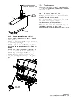
12.4.3.5. Thread the optical port dust cap into the drop
cable dust cap as shown below and then tighten both
dust caps finger tight. This ensures that both dust caps
will stay clean when not in use.
12.5. Disconnecting the drop cable from
the indexing terminal (full size
hardened connector housing)
adapter port
Danger: Exposure to laser radiation can seriously
damage the retina of the eye. Do not look into the ends
of any optical fiber. Do not assume the laser power is
turned-off or that the fiber is disconnected at the other
end.
12.5.1. Unscrew the optical port dust cap from the drop
cable dust cap.
12.5.2. Unscrew the drop cable connector coupling nut
from the optical port and pull the connector straight out
the adapter.
12.5.3. Inspect the optical port dust cap O-ring for
dryness and apply O-ring lubricant (MST-ACC-LUBE1)
to the O-ring if dry. Refer to Section 12.6 for the required
procedure.
12.5.4. Thread the optical port dust cap into the optical
port and tighten using the 216B key tool.
12.5.5. Inspect the drop cable connector O-rings for
dryness and apply O-ring lubricant (MST-ACC-LUBE1) to
each O-ring if dry. Refer to Section 12.6 for the required
procedure.
12.5.6. Thread the drop cable dust cap onto the drop
cable connector coupling nut and tighten until finger tight.
12.6. Applying O-ring lubricant
The O-rings used on the hardened connector and on
the optical port dust cap are lubricated when shipped
from the factory to prevent damage during installation.
If the O-rings become excessively dry, they may require
additional lubrication to prevent damage. Remove the
O-rings from the connector or dust cap and apply a small
amount of lubricant directly to each ring. Then reinstall
the O-rings on the connector or dust cap. Apply only the
recommended O-ring lubricant (MST-ACC-LUBE1).
Note:
Excessive lubricant on the o-ring may cause
contamination of fiber endface.
DROP CABLE
DUST CAP
OPTICAL PORT
DUST CAP


