
16
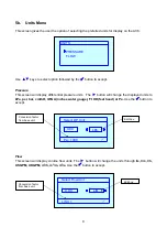
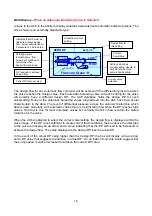
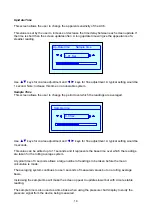
View Size As
This screen allows the user to select the preferred units for selecting valve size. The default unit is
metric (mm).
Use the
▲▼
keys to select option followed by
button to accept.
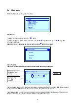
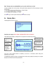
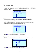
6. ‘Quick Valve’ Storing Function
.
This display allows the user to save the data from the current valve to a project. To use this feature
press the
button whilst viewing any of the display screens.
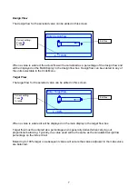
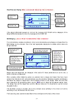
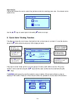
The project can be made up from up to ten groups of valves, each with ten valves. The group
number can be selected using the
▲▼
keys and the valve number can be selected using the
◄►
keys.
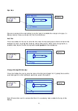
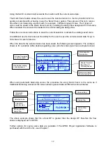
The
MENU
button gives the user the option to save or delete. If the screen is black, a valve is
already in the location. However, if the screen is white it is possible to load a valve to this location.
MM
Inches
View size as
MENU
TO EXIT
Group 1 Valve 1
0.00 kPa
0.000 l/s
Group No. - 10
Groups available.
Valve No.-10 valves
per group available.
Use
▲▼
keys to
select group.
Use
◄►
keys to
select valve No.
DP and flow data
for selected valve.
Use
MENU
when group
and valve No. have
been selected.
Group 1 Valve 1
Load
Clear
Save
Exit


