15
Compressed Air Supply
It is important for proper operation of both, the dry ice blaster and the abrasive blaster, that the
incoming air is connected properly. The abrasive media system has a pressure rating of 150 psi
(10.3 bar). It is therefore necessary that the blast pressure of the dry ice blaster be set no higher
than 135 psi (9.3 bar). If the dry ice blaster is not equipped with a pressure regulator then the
incoming supply pressure must not exceed 140 psi (9.6 bar). There are two 150 psi (10.3 bar) safety
pressure relief valves that will pop if these pressures are exceeded.
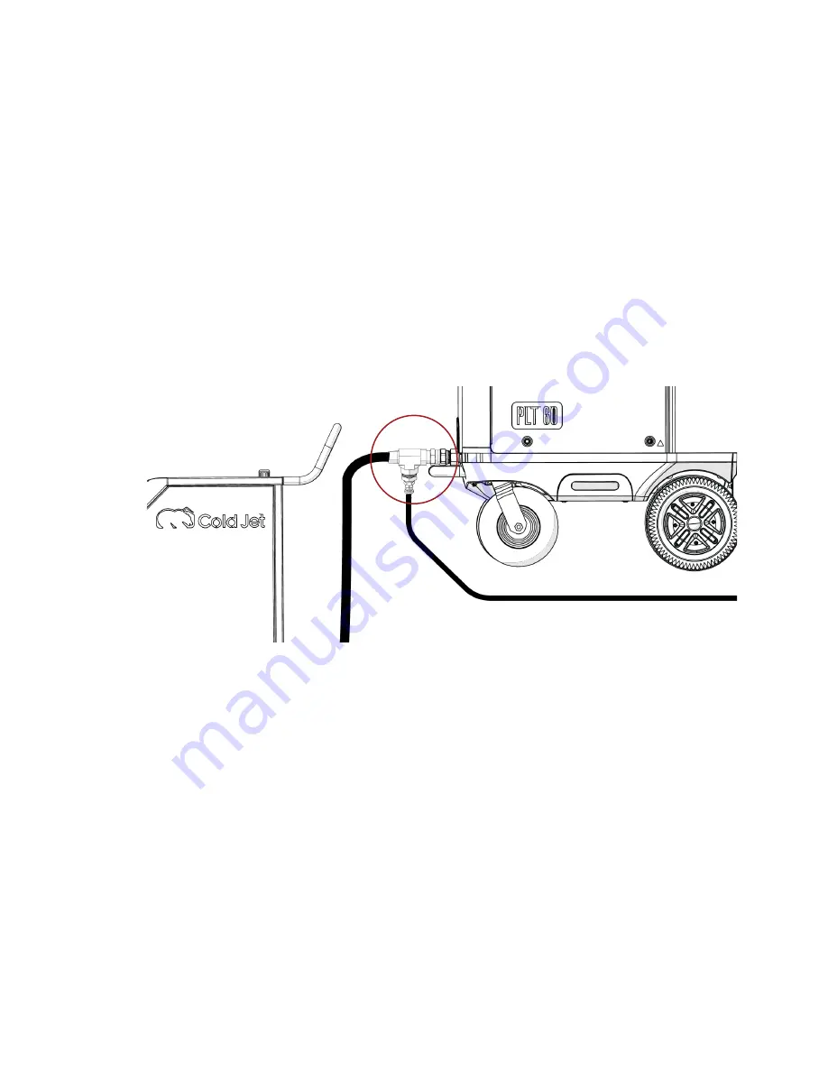
Figure 4 shows the connector that goes between the compressed air source and the dry ice blaster.
It will come supplied connected to the abrasive system with the small hose. The threaded end will
attach to the inlet of the dry ice blaster and the swivel end will attach to the supply hose. The whip
check should slip over the supply hose. It may be possible that your hose or dry ice blaster has a
different fitting – if so, it will be up to you to supply the correct fitting(s).
Figure 4: Compressed Air Splitter
Using Plant Air
(Central Compressed Air System)
Manufacturing plants, with central compressed air systems, should have an After Cooler and
a 2-stage coalescing filter assembly downstream of the receiver tank. Hot metal pipes are an
indication this is needed.
To verify that the plant air system is adequate for the blaster and the Aero E-CO
2
150 the air
compressor needs to produce an air volume 10% greater than the blast machine’s maximum air
volume in addition to the air volume consumed by normal plant operation.
To determine adequate air volume, watch the pressure gauge or digital pressure display while blasting.
y
If the gauge drops slowly the compressor is
insufficient.
y
If the gauge drops quickly there is a restriction
or the pipe is too small.
y
If the gauge stays steady then the compressor and piping are adequate.
Содержание E-CO2 150
Страница 1: ...Original Instructions English January 2020 Dry Ice Blasting Abrasive E CO2 150 Operator Manual...
Страница 4: ......
Страница 23: ...19 Aero C100 Connections Figure 7 Aero C100 Connections Aero 80FP Connections Figure 8 Aero 80FP Connections...
Страница 37: ...33 Technical Schematics Pneumatic Schematics 34 39...
Страница 38: ...34...
Страница 39: ...35 C100 E CO2 150 Schematic...
Страница 40: ...36...
Страница 41: ...37 Aero 80FP E CO2 150 Schematic...
Страница 42: ...38...
Страница 43: ...39 PLT 60 E CO2 150 Schematic...
Страница 44: ......


