background image

1891f-enu_Ersatzteile.fm, 25.04.2014

P1891E/EN 2014-02

71

Spare parts

10

Equipment order list

Index

Order no.

Designation

A

933450

Reassembly of output spindle

A1

933451

Punch

A2

933453

Base

A3

933452

Punch

B

933454

Reassembly of bevel gear spindle

B1

933455

Punch

B2

933456

Base

C

933449

Reassembly of bevel gear spindle 
in angle attachment

B1

933455

Punch

C2

933463

Half-shell pair

C3

933458

Base

D

933448

Disassembly of bevel gear spindle

D1

900009

Cap screw M6×25

D2

933459

Thrust pad

D3

933460

Sleeve

D4

933461

Pull-out bolt

D5

933462

Half-shell pair

E

933428

Socket wrench socket SW 24; 2-edge

F

933427

Socket wrench socket D16

G

938616PT

Clamping jaws for LiveWire2

47BA(…)15(…)L
47BA(…)21(…)L
47BA(…)28(…)L

938617PT

Clamping jaws for LiveWire2

47BA(…)35(…)L
47BA(…)50(…)L

Z

933336

Hook wrench
Angle attachment - gearing fastening

Содержание LiveWire P1891E

Страница 1: ...For additional product information visit our website at http www apextoolgroup com 47BA B Cordless EC tool Instruction Manual P1891E EN 2014 02...

Страница 2: ...ng with this tool without carrying out programming work The instruction manual has the following purposes provides important instructions for safe and effective operation describes the function and op...

Страница 3: ...LiveWire 1 described here 47BA L stands for all versions of the cordless EC tool LiveWire 2 described here EV stands for all versions of the power supply described here Battery pack or Power module L...

Страница 4: ...4 P1891E EN 2014 02 1891a enu_deckblatt fm 25 04 2014...

Страница 5: ...tems supplied 10 2 2 Transport 10 2 3 Storage 10 3 Product description 11 3 1 General description 11 3 2 Operation and functional elements 12 4 Accessories 17 5 Before initial operation 18 5 1 Use of...

Страница 6: ...k 15 Nm 28 Nm 64 10 4 Angle attachment 525943 AM3 with pin lock 35 Nm 50 Nm Angle attachment 541174 AM3B with ball lock 35 Nm 50 Nm 66 10 5 Angle attachment 937776PT P4 with pin lock 70 Nm 90 Nm 68 10...

Страница 7: ...injury may occur CAUTION Indicates a potentially hazardous situation which if not avoided may result in minor or moderate injury or property and environmental damage If this warning is not observed i...

Страница 8: ...mmissioning the 47BA 47BA tightly in the hand be prepared for high short term reaction torques Always use a reaction bar for applications in restricted space and torques over 68 Nm This prevents injur...

Страница 9: ...res which cause unwanted operation of the device Changes or modifications not expressly approved by the party responsible for compliance could void the user s authority to operate the equipment 1 6 2...

Страница 10: ...rmity 1 Factory test certificate for transducers 1 Machine Capability Analysis MCA 2 2 Transport 47BA in the original packaging The packing is recyclable 2 3 Storage For short term storage and for pro...

Страница 11: ...stening parameters are set with the controller or a PC An exchangeable memory module LiveWire Memory Chip allows the quick exchange of identical tools without changing the parameters Depending on the...

Страница 12: ...2 2 6 3 2 Item Designation 1 Function keys F1 F2 2 LED display 3 Start button 4 Reverse switch 5 IrDA infrared interface port 6 Set torque stick on marking foil 7 LED lights for fast location of the f...

Страница 13: ...2 LED display The LED display shows the respective operating status and the result of the last fastening sequence see 6 2 Operating status page 21 Software update During Software Update the actual pro...

Страница 14: ...e 47BA communicates with the control about the tool holder via the IrDA interface port infrared For secure data transmission and for programming the 47BA place the 47BA in the tool holder with IrDA in...

Страница 15: ...undowns From the Scanner tool menu select Read barcode Press the start button on the tool this activates the barcode scanner The successful scan is acknowledged by an acoustic signal Press the start b...

Страница 16: ...from the LMC chip and used to establish the WLAN connection When the tools are changed the LMC has to be installed in the new tool being used Please refer to 5 5 Changing LMC page 19 The following dat...

Страница 17: ...r no 961342 060 6 m Order no 961342 080 8 m Order no 961342 100 10 m with IrDA interface RS232 connection cable Order no 935290 to 50 Nm Order no 935999 from 70 Nm Without IrDA interface RS232 connect...

Страница 18: ...utside light shines onto the tool holder This can inhibit data transmission Lay the connection cable in such a way that there is no danger that persons can trip 5 3 Ambient conditions 5 4 Charge batte...

Страница 19: ...is a potential equalization between the person and the tool Possibly set up equipment in an ESD protected environment Recom mendation for an ESD workplace Electrically conductive work surfaces anti s...

Страница 20: ...e Press and release the start button rundown is executed the LCD display shows Ready Types with wireless transmission continuously communicate with the controller The tool automatically receives the p...

Страница 21: ...Gr n Verschraubung OK On Screws Data transmission Automatic switch to the following after 1 minute1 idle time 1 Times are default values and can be programmed in the control Energy saver mode Green f...

Страница 22: ...22 P1891E EN 2014 02 1891b enu_1_5_bedingt fm 25 04 2014 Initial operation 6 Empty side...

Страница 23: ...erload in output section IIT Requested motor output is too high TMAX Maximum fastening time exceeded RC Rundown terminated by disabled start signal Tq Torque too low Tq Torque too high WI Angle too sm...

Страница 24: ...rundown data have to be transmitted to the control Emergency mode active Indicates that the emergency mode is currently enabled and thus that no connection to the control must exist A maximum of 512 r...

Страница 25: ...ol with the control for the first time The Tool Enable input is missing Set the Tool Enable input Synchronize the tool with the control once again This message can appear only if External Tool Enable...

Страница 26: ...e Number of repetitions at this position in case of an NOK rundown Linking has been canceled without a batch result Not all of the positions in the tightening group have been programmed Check the Appl...

Страница 27: ...menus can be disabled by configuring appropriate parameter in the controller Basic functions F2 Activate main menu F1 Go to previous menu item F2 Go to next menu item Press F1 longer than 2 seconds t...

Страница 28: ...s transmission Software version Back Servo Emergency mode Platform Back Diagnosis TQ calibration TQ measurement Angle encoder Voltages Speed Back Set position Next position Reset Linking Back Scanner...

Страница 29: ...4 P1891E EN 2014 02 29 LCD display 7 868 MHz 47BAR Wireless module version Channel Network ID Tool ID Power Back RF15 4 47BA Z Channel PAN ID Tool ID Power Encryption Serial no of wireless mod Wireles...

Страница 30: ...ounter display etc Diagnostic functions for the tool Position Selects the position to be used next Deletes a previously read barcode and activates a new read cycle Shows Settings LiveWire Memory Chip...

Страница 31: ...ad Optional Active when service counter was activated by Apex Tool Group Number of rundowns until next service Serial number Serial no display Refer to Serial number on the Control under Tool or Diagn...

Страница 32: ...gency mode active Is displayed during fastening Only for models of the 47BAYP series Activating add on parts fitted on platform scanner TAG TQ calibration This test function cyclically recalibrates th...
Страница 33: ...ther the output shaft has actually turned by the value indicated e g by placing a mark on the spindle If the angle reached by the output shaft does not agree with the value displayed either the angle...

Страница 34: ...be used next You can skip the position You can select the position to be used next using the function keys F1 Activate the previous position F2 Activate the next position Press the start button or F2...

Страница 35: ...of current quality of wireless signal via function key F1 When the start button is pressed the current strength of the wireless signal is displayed as an RSSI value S Signal strength dBm N Signal stre...

Страница 36: ...onds to delete the selection and exit the menu The channel must match the set channel of the base station Defines the network identification You can operate no more than 4 tools per network ID F1 Acti...

Страница 37: ...nd 25 mW for the transmission power If channel 2 or 3 is selected you can choose either 1 or 5 mW for the transmission power Press the start button or F2 longer than 2 seconds to accept the selection...

Страница 38: ...ct a channel from 1 4 Start button show tool ID default 1 F1 Activate a lower network ID F2 Activate a higher network ID Press the start button or F2 longer than 2 seconds to accept the selection and...

Страница 39: ...d exit the menu On Off must match the preset PAN ID of the base station Displays the wireless module serial number Displays the firmware and hardware version of the RF15 4 module Displays the current...

Страница 40: ...n re insert it If this does not help Return tool to Sales Service Centers for repair Speed specification from the measuring board to the servo is faulty Remove the battery and then re insert it If thi...

Страница 41: ...Service Centers for repair Current at servo output stage is too high There may be a short circuit Return tool to Sales Service Centers for repair Tool angle encoder is sending incorrect signals to the...

Страница 42: ...in If this does not help Return tool to Sales Service Centers for repair Transducer offset voltage error Tool was not discharged at time of calibration Allow tool to discharge and try again If this do...

Страница 43: ...account CAUTION Danger of injury through unintentional activation prior to servicing 47BA disconnect power supply After fastening cycles1 2 Measures 100 000 Check to ensure the battery adapter scanne...

Страница 44: ...ecalibration of tool see 12 1 Recalibration Seite 86 2 5 million General refurbishment of tool Send it to Sales Service Centers 1 For the number of fastening cycles refer to the counter display in 7 3...

Страница 45: ...pment order list Seite 71 If the 47BA is opened the warranty is voided Only specialized technicians should be allowed to open the gear for servicing Carefully clamp the 47BA in a vice see illustration...

Страница 46: ...891E EN 2014 02 1891d enu_Wartung fm 25 04 2014 Servicing 8 8 5 Removing angle attachment 935313 1 2 3 4 Index see 10 Spare parts Seite 59 Equipment order list Seite 71 D5 D4 29 C2 D5 D4 29 D5 D3 D2 D...

Страница 47: ...4 P1891E EN 2014 02 47 Servicing 8 8 6 Installing angle attachment 935313 Output spindle Bevel gear spindle 1 2 3 4 Index see 10 Spare parts Seite 59 Equipment order list Seite 71 31 30 A2 A1 A3 29 A2...

Страница 48: ...P1891E EN 2014 02 1891d enu_Wartung fm 25 04 2014 Servicing 8 Bevel gear and drive spindle in angle attachment 5 6 Index see 10 Spare parts Seite 59 Equipment order list Seite 71 36 C3 B1 26 27 29 28...

Страница 49: ...ntrol screen Advanced Tool Settings LiveWire Settings mark the check box Enable Tool Menu or use the drop down list F1 Button on Tool to assign the left function key F1 Press on the control Select the...

Страница 50: ...RDA Con nection Check whether the tool holder is connected at the selected inter face Selected interface is used for serial data transmission Do not use the same interface for serial data transmission...

Страница 51: ...point On the control screen Tool Setup RF Settings check whether the WLAN settings for the tool agree with the settings for the access points network name encryption network key On the control screen...

Страница 52: ...ntrol Excessive data traffic on WLAN Network Reduce data traffic on WLAN Network On the control screen Basic increase the Initial Torque On the control screen mPro Main Menu System Pro gramming Specia...

Страница 53: ...m Pro gramming Serial Ports Disable serial data transmis sion All tools must be checked Supply voltage not active Check the socket to which the power supply unit for the base sta tion is connected No...

Страница 54: ...the tool and check whether communication is possible If so increase the power on the base station and tool or reduce the distance between the base station and the tool 868 MHz data commu nication occa...

Страница 55: ...ed for the con nection to the control ler On the control screen Tool Setup Wireless Settings Check RF Mode On the control screen Main Menu System Programming Service TMA Configuration Communication wi...

Страница 56: ...ncrease the power on the base station and tool or reduce the distance between the base station and the tool Transmission power is too low Increase the power on the base station and tool Excessive data...

Страница 57: ...ed Tool Settings LiveWire Settings F1 Button on Tool select Read Bar code Press on the control Select the required scanner under Station Identifi cation Select the required tool under TM Unit Tool Ass...

Страница 58: ...y back to the current fastening job 1 2 3 4 Press F1 F2 at the same time and hold Press start button 1 and release Release F2 Keep F1 pressed and continue with step 3 Press F2 3 and release Keep F1 pr...

Страница 59: ...ts Always use only original Cleco spare parts Failure to comply with this instruction can result in decreased performance and an increased need for servicing Installing spare parts from other manufact...

Страница 60: ...313 47BA 15AM3B 941568 47BA 21AM3 935262 542722 541893 542231 541888 541894 923095 542079 935313 47BA 21AM3B 941568 47BA 28AM3 935261 542722 541893 542232 541888 541897 923095 542099 935313 47BA 28AM3...

Страница 61: ...1891f enu_Ersatzteile fm 25 04 2014 P1891E EN 2014 02 61 Spare parts 10 1 Order no 2 Quantity lRecommended spare part for every 5 tools 3 Dimension TAB 1see Table Seite 60...

Страница 62: ...ngle attachment 8 3 Lubricants Seite 44 TAB 2 Type 40 39 30 28 24 47 47BAYB70P4 937776PT 942005PT 541279 541474 3 543456 47BAYSB70P4 47BAYPB70P4 47BAYB70P4B 937779PT 47BAYSB70P4B 47BAYPB70P4B 47BAYB90...

Страница 63: ...1891f enu_Ersatzteile fm 25 04 2014 P1891E EN 2014 02 63 Spare parts 10 1 Order no 2 Quantity 3 Dimension lRecommended spare part for every 5 tools TAB 2see Table Seite 60...

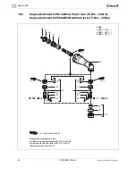
Страница 64: ...941568 AM3B with ball lock 15 Nm 28 Nm 24 26 28 29 29 27 25 32 43 33 42 34 41 37 38 39 31 44 30 30 36 941146 941146 941146 3 8 3 8 941568 935313 Reassembly disassembly see 8 5 Removing angle attachmen...

Страница 65: ...1891f enu_Ersatzteile fm 25 04 2014 P1891E EN 2014 02 65 Spare parts 10 1 Order no 2 Quantity 3 Dimension lRecommended spare part for every 5 tools...

Страница 66: ...t 525943 AM3 with pin lock 35 Nm 50 Nm Angle attachment 541174 AM3B with ball lock 35 Nm 50 Nm Always replace 15 and 16 as a set 3 8 541174 3 8 525943 1 1 11 23 OFF 54 68 Nm 40 50 lbf ft 31 75 1 25 Lo...

Страница 67: ...1891f enu_Ersatzteile fm 25 04 2014 P1891E EN 2014 02 67 Spare parts 10 1 Order no 2 Quantity lRecommended spare part for every 5 tools 3 Dimension...

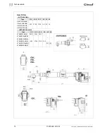
Страница 68: ...02 1891f enu_Ersatzteile fm 25 04 2014 Spare parts 10 10 5 Angle attachment 937776PT P4 with pin lock 70 Nm 90 Nm 10 6 Angle attachment 937779PT P4B with ball lock 70 Nm 90 Nm Type 47BA 70 47BA 90 Typ...

Страница 69: ...2014 P1891E EN 2014 02 69 Spare parts 10 10 7 Use with reaction bar 1 2 hexagonal 1 Order no 2 Quantity 3 Dimension lRecommended spare part for every 5 tools Is provided and adjusted by user see 5 1 U...

Страница 70: ...s 10 10 8 Tool holder 1 Order no 2 Quantity 3 Dimension lRecommended spare part for every 5 tools TAB 8see Table TAB 8 Order no IrDA For Tool 47 52 53 54 935290 to 47BA 50AM3 935292 935303 935170 9177...

Страница 71: ...gear spindle in angle attachment B1 933455 Punch C2 933463 Half shell pair C3 933458 Base D 933448 Disassembly of bevel gear spindle D1 900009 Cap screw M6 25 D2 933459 Thrust pad D3 933460 Sleeve D4...

Страница 72: ...72 P1891E EN 2014 02 1891f enu_Ersatzteile fm 25 04 2014 Spare parts 10...

Страница 73: ...5AM3 B 47BAYB15AM3 B 47BAYPB15AM3 B 52 5 8 5 47BAZB15AM3 B 47BARB21AM3 B 47BAXB21AM3 B 47BAYB21AM3 B 47BAYPB21AM3 B 52 5 8 5 47BAZB21AM3 B 47BARB28AM3 B 47BAXB28AM3 B 47BAYB28AM3 B 47BAYPB28AM3 B 52 5...

Страница 74: ...canner without scanner Type L1 1 L1 2 L1 3 L2 L3 L4 47BARSB35AM3 B 600 570 8 578 8 14 2 43 18 47BAXSB35AM3 B 47BAYSB35AM3 B 47BAZSB35AM3 B Type L1 1 L1 2 L1 3 L2 L5 L6 47BAB35AM3 B 585 5 556 3 564 3 4...

Страница 75: ...scanner without scanner Type L1 1 L1 2 L1 3 L2 L3 L4 47BARSB50AM3 B 608 578 8 586 8 14 2 43 18 47BAXSB50AM3 B 47BAYSB50AM3 B 47BAZSB50AM3 B Type L1 1 L1 2 L1 3 L2 L5 L6 47BAB50AM3 B 594 564 8 572 8 47...

Страница 76: ...Technical data 11 Gear 70 Nm 90 Nm without scanner with scanner mit platform Type L1 1 L1 2 47BAYB70P4 47BAYB70P4B 47BAYB90P4 47BAYB90P4B Type L1 1 L1 2 47BAYSB70P4 47BAYSB70P4B 47BAYSB90P4 47BAYSB90...

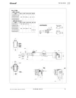
Страница 77: ...N 2014 02 77 Technical data 11 11 2 LiveWire 2 Dimensions 47BAYPB L mm Type L1 1 L1 2 L1 3 L2 L3 with scanner tag 47BAYPB15AM3 B 563 535 9 544 123 16 9 47BAYPB21AM3 B 47BAYPB28AM3 B 47BAYPB35AM3 B 595...

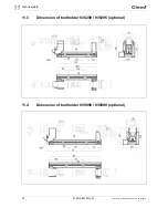
Страница 78: ...78 P1891E EN 2014 02 1891g enu_TechnDaten_bedingt fm 25 04 2014 Technical data 11 11 3 Dimension of tool holder 935290 935395 optional 11 4 Dimension of tool holder 935999 935998 optional...

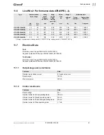
Страница 79: ...B15AM3 B 2 14 47BARB15AM3 B 47BAXB15AM3 B 47BAYB15AM3 B 47BAYPB15AM3 B 47BAZB15AM3 B 47BABSB15AM3 B 2 20 47BARSB15AM3 B 47BAXSB15AM3 B 47BAYSB15AM3 B 47BAZSB15AM3 B 47BAB21AM3 B 21 8 411 751 M7 2 04 2...

Страница 80: ...3 B 47BABSB50AM3 B 2 48 47BARSB50AM3 B 47BAXSB50AM3 B 47BAYSB50AM3 B 47BAZSB50AM3 B 47BAYB70P4 70 24 121 211 M10 4 12 98 79 4 4130 47BAYSB70P4 4 18 47BAYPB70P4 4 19 47BAYB70P4B 4 12 47BAYSB70P4B 4 18...

Страница 81: ...on data without PS1 1 Weight of power supply battery pack 26 V 935377 0 50 kg battery pack 44 V 936400PT 0 85 kg Torque nominal Angle pulses Resolver Nm max Nm min rpm rpm mm kg Nm 1 degrees 47BAYPB15...

Страница 82: ...3 97 cm 5 mil 3 18 20 32 cm 7 5 mil 3 81 33 66 cm 10 mil 3 81 44 45 cm 100 3 81 59 69 cm 15 mil 3 81 74 93 cm 20 mil 4 45 90 17 cm 40 mil 1 101 60 cm 55 mil 1 139 70 cm 1 Depending on the width of the...

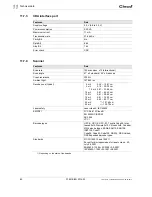
Страница 83: ...rds ETSI EN 300 328 V1 7 1 EN 301489 1 V1 6 1 EN 301489 3 V1 4 1 EN 50392 2004 FCC Part 15 247 RSS 210 Features Data Frequency 868 870 MHz Channels Band 1i 869 4 MHz 869 65 MHz Band 1k 869 7 MHz 870 0...

Страница 84: ...WPA2 AES CCMP 802 1x EAP authentication LEAP PEAP1 TLS GTC MD5 OTP PAP CHAP MSCHAP MSCHAPv2 TTLS MSCHAPv2 1 PEAP without client certificate Range Typically up to 50 m Channels 1 11 2 412 2 462 GHz Tra...

Страница 85: ...40 44 48 52 56 60 64 100 104 108 112 116 132 136 140 149 153 157 161 165 5 180 5 825 GHz Transmission power 20 dBm typ 2 4 GHz 15 dBm typ 5 0 GHz Sensitivity 94 dBm typ 1 Mbps 2 4 GHz 80 dBm typ 5 GH...

Страница 86: ...Disposal CAUTION Injuries and environmental damage from improper disposal Components and auxiliary materials of the tool pose risks to the health and the environment Catch auxiliary materials oils gr...

Страница 87: ......

Страница 88: ...s Service Center 3990 East Market Street York PA 17402 USA Phone 1 717 755 2933 Fax 1 717 757 5063 France Apex Tool Group SNC 25 Rue Maurice Chevalier BP 28 77831 Ozoir la Ferri re Cedex France Phone...

Отзывы: