


Citrix ADC MPX
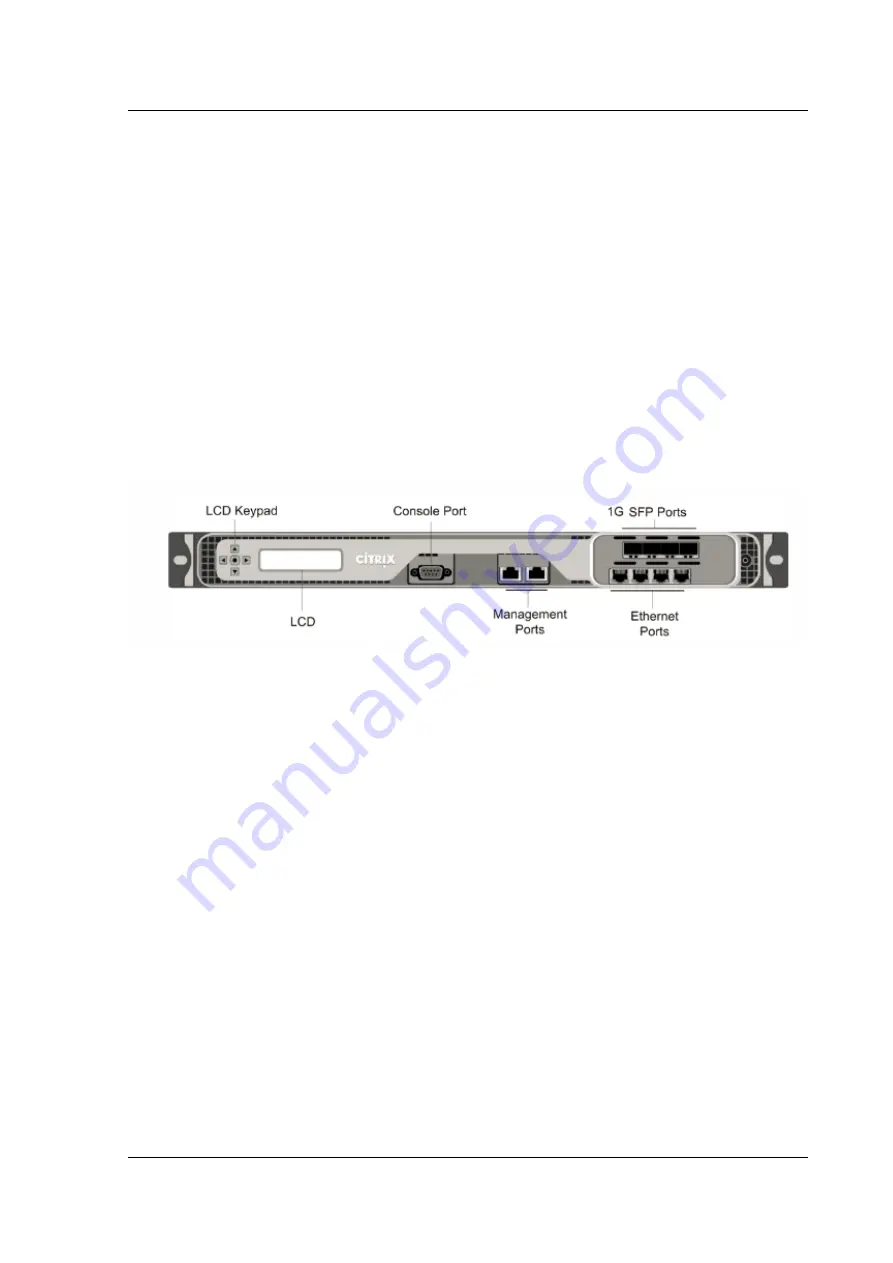
• Two 10/100/1000Base-T copper Ethernet management ports, numbered 0/1 and 0/2 from left
to right. These ports are used to connect directly to the appliance for system administration
functions.
• Network Ports
–
MPX 7500/9500 (8x10/100/1000Base-T copper Ethernet ports). Eight 10/100/1000Base-T
copper Ethernet ports numbered 1/1, 1/2, 1/3, and 1/4 on the top row from left to right, and
1/5, 1/6, 1/7, and 1/8 on the bottom row from left to right.
–
MPX 7500/9500 (4x1G SFP + 4x10/100/1000Base-T copper Ethernet ports). Four 1-gigabit
copper or fiber 1G SFP ports numbered 1/1, 1/2, 1/3, and 1/4 on the top row from left to right,
and four 10/100/1000BASE-T copper Ethernet ports (RJ45) numbered 1/5, 1/6, 1/7, and 1/8
on the bottom row from left to right.
The following figure shows the back panel of the MPX 7500/9500 appliance.
Figure 3. Citrix ADC MPX 7500/9500, back panel
The following components are visible on the back panel of the MPX 7500
/9500:
• Four-gigabyte removable CompactFlash card that is used to store the Citrix ADC software.
• Power switch, which turns off power to the MPX 7500/9500, just as if you were to unplug the
power supply. Press the switch for five seconds to turn off the power.
• Removable hard-disk drive (HDD) that is used to store user data. Appliances shipped before
February, 2012 store user data on a HDD. In appliances shipped after February, 2012, a solid-
state drive replaces the HDD. Both types of drive have the same functionality and support the
same software releases.
• USB port (reserved for a future release).
• Non-maskable interrupt (NMI) button that is used at the request of Technical Support and pro-
duces a core dump on the appliance. You must use a pen, pencil, or other pointed object to
press this red button, which is recessed to prevent unintentional activation.
• Disable alarm button. This button is functional only when the appliance has two power sup-
plies.
© 1999-2019 Citrix Systems, Inc. All rights reserved.
33


