3-24
Cisco UCS C3160 Rack Server Installation and Service Guide
OL-32062-01
Chapter 3 Maintaining the System
Installing or Replacing System Components
Replacing Fan Modules
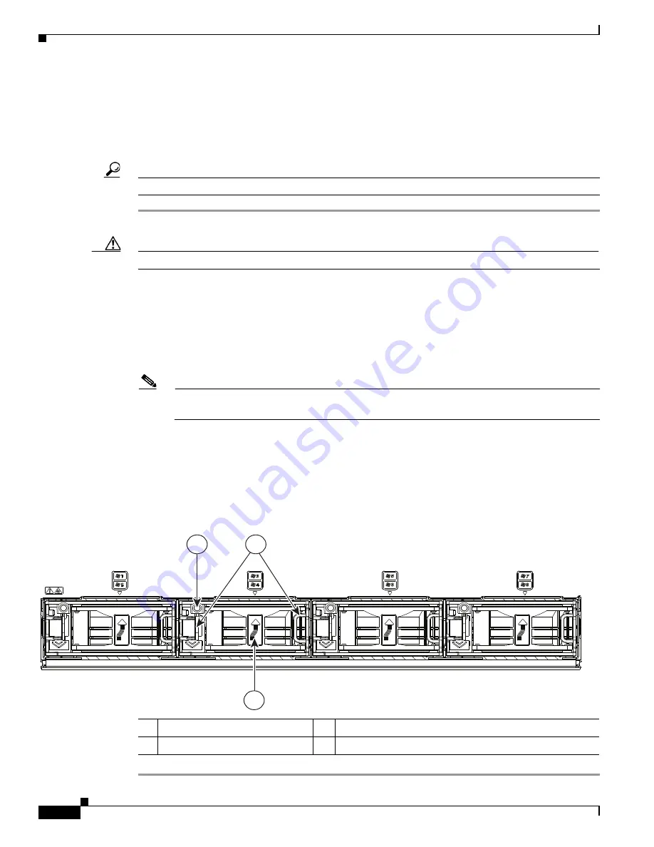
Each fan module contains two fans. See
Figure 3-14
for the fan numbering. The odd-numbered fan is at
the top of the fan module and the even-numbered fan is at the bottom of the fan module.
You do not have to shut down or power off the system to replace fan modules because they are
hot-swappable.
Tip
Each fan module has a fault LED that lights amber if the fan module fails.
Step 1
Slide the system out the front of the rack far enough so that you can open the fan compartment cover.
Caution
If you cannot safely view and access the component, remove the system from the rack.
Step 2
Open the fan compartment cover as described in
Opening the Main Chassis Top Covers, page 3-10
.
Step 3
Remove a fan module:
a.
Grasp the two latches on the top of the fan and pinch them toward the center.
b.
Lift the fan module straight out of the bay.
Step 4
Install a new fan module:
Note
The arrow on the fan module that indicates the air flow direction should point to the rear of the
server.
a.
Align the fan module with the bay so that the connector on the bottom of the fan module is aligned
with the socket on the floor of the chassis.
b.
Lower the fan module until it touches the socket, then push down firmly until the latch locks.
Step 5
Close the fan compartment cover and then push the system back into the rack.
Figure 3-14
Fan Modules (Top View)
1
Fan module fault LED
3
Air flow direction arrow pointing toward rear of server
2
Fan module release latches
353457
1
2
3
Содержание UCS C3160
Страница 6: ...Contents vi Cisco UCS C3160 Rack Server Installation and Service Guide OL 32062 01 ...
Страница 10: ...x Cisco UCS C3160 Rack Server Installation and Service Guide OL 32062 01 ...
Страница 12: ...xii Cisco UCS C3160 Rack Server Installation and Service Guide OL 32062 01 ...
Страница 13: ...xiii Cisco UCS C3160 Rack Server Installation and Service Guide OL 32062 01 ...


