background image

E-5

Cisco 7600 Series Router Installation Guide

OL-4503-26

Appendix E      Cisco 7606-S DC Power Supply Configurations

Cisco 7606-S V02 Configuration with a 2700 W DC Power Supply and a 4500 W DC Power Supply

Step 7

Install the 4500 W DC in the lower slot as described in 

Installing a PWR-4500-DC Power Supply in a 

Cisco 7606-S Router, page 5-61

.

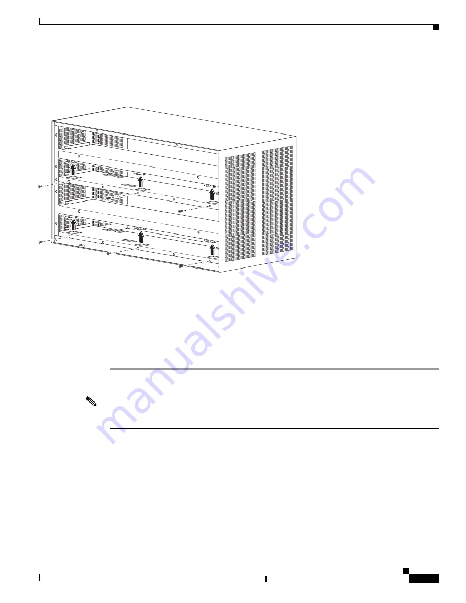
Figure E-4

Removing Booster Brackets

Cisco 7606-S V02 Configuration with a 2700 W DC Power Supply 
and a 4500 W DC Power Supply

This configuration requires you to remove the lower booster bracket (Part Number 800-31261-01).

Step 1

Remove the PWR-2700-DC power supply from the lower slot as described in 

Removing PWR-2700-DC 

Power Supply from a Cisco 7606-S Router, page 5-19

.

Note

When you are using a PWR-2700-DC and a PWR-4500-DC, you must install the PWR-4500-DC supply 
in the lower slot. 

Step 2

Remove three screws (Part Number 48-2454-01) securing the booster  bracket (Part Number 
800-31261-01) at the bottom slot See. 

Figure E-4

.

Step 3

Push the booster  bracket (Part Number 800-31261-01) backward and then lift and remove it from the 
chassis.

Step 4

Install the 4500 W DC in the lower slot as described in 

Installing a PWR-4500-DC Power Supply in a 

Cisco 7606-S Router, page 5-61

.

253054

Cisco 7600 

Series

Содержание 7606

Страница 1: ... Cisco Systems Inc 170 West Tasman Drive San Jose CA 95134 1706 USA http www cisco com Tel 408 526 4000 800 553 NETS 6387 Fax 408 527 0883 Cisco 7600 Series Router Installation Guide October 2010 Text Part Number OL 4503 26 ...

Страница 2: ...y from the television or radio Plug the equipment into an outlet that is on a different circuit from the television or radio That is make certain the equipment and the television or radio are on circuits controlled by different circuit breakers or fuses Modifications to this product not authorized by Cisco Systems Inc could void the FCC approval and negate your authority to operate the product The...

Страница 3: ...echnical Assistance Center xvii Obtaining Additional Publications and Information xviii C H A P T E R 1 Product Overview 1 1 This publication describes the following Cisco 7600 series routers 1 1 Cisco 7603 Router 1 2 Cisco 7603 S Router 1 3 Cisco 7604 Router 1 5 Cisco 7606 Router 1 7 Cisco 7606 S Router 1 10 Cisco 7609 Router 1 12 Cisco 7609 S Router 1 13 Cisco 7613 Router 1 14 System Features 1 ...

Страница 4: ...acket 3 4 Installing the Chassis Brackets 3 5 Installing the Router Chassis in the Rack 3 9 Installing the Stabilizer Kit Cisco 7609 Router Cisco 7609 S and Cisco 7613 Router Only 3 13 Installing the Cable Management System Cisco 7609 Router and Cisco 7609 S Router Only 3 15 Replacing the Cable Guide 3 17 System Ground Connection 3 19 Required Tools and Equipment 3 20 Connecting the System Ground ...

Страница 5: ...5 114 Removing a DC Input PEM 5 114 Installing a DC Input PEM 5 116 Removing and Replacing the Fan Assembly 5 118 Removing the Fan Assembly 5 118 Installing the Fan Assembly 5 124 Checking the Installation 5 125 Installing the Air Filter Assembly on a Cisco 7606 Router and the Cisco 7606 S Router Optional 5 125 Installing the Air Filter Assembly on a Cisco 7609 Router and the Cisco 7609 S Router O...

Страница 6: ...le Port Mode Switch B 7 Identifying a Rollover Cable B 8 Console Port Mode 1 Signaling and Pinouts B 8 Console Port Mode 2 Signaling and Pinouts B 10 Mode Conditioning Patch Cord B 10 A P P E N D I X C Configuration Register Information C 1 Configuration Bit Meanings C 1 Bits 0 3 C 2 Bit 6 C 3 Bit 7 C 3 Bit 8 C 4 Bit 10 and Bit 14 C 4 Bit 11 and Bit 12 C 4 Bit 13 C 4 Bit 15 C 5 Displaying the Conf...

Страница 7: ...onfigurations E 1 Cisco 7606 S V01 Configuration with Two 2700 W DC Power Supplies E 1 Cisco 7606 S V01 Configuration with Two 4500 W DC Power Supplies E 2 Cisco 7606 S V01 Configuration with a 2700 W DC Power Supply and a 4500 W DC Power Supply E 3 Cisco 7606 S V02 Configuration with Two 2700 W DC Power Supplies E 4 Cisco 7606 S V02 Configuration with Two 4500 W DC Power Supplies E 4 Cisco 7606 S...

Страница 8: ...Contents viii Cisco 7600 Series Router Installation Guide OL 4503 26 ...

Страница 9: ...oduct number OSR 7609 is in the Cisco 7609 Router Installation Guide located at this URL http www cisco com univercd cc td doc product core cis7600 hardware osrouter index htm Document Revision History Revision Date Change Summary OL 4503 26 October 2010 Added new troubleshooting information in Chapter 4 Troubleshooting OL 4503 25 July 2010 Added clearance guidelines when planning to install or re...

Страница 10: ...x A OL 4503 20 December 2005 Added Supervisor Engine 32 Added 19 rack information to Installing the Chassis Brackets in Chapter 3 OL 4503 19 September 2005 Added new cable information to 2700 W Power Supply PWR 2700 AC in Chapter 2 OL 4503 18 April 2005 Added PWR 2700 AC 4 for Cisco 7604 OL 4503 17 April 2005 Added 6000 W AC input WS CAC 6000W information to Chapters 1 2 and 5 and to Appendix A Ad...

Страница 11: ...e to Chapter 1 Revision Date Change Summary Chapter Title Description Chapter 1 Product Overview Describes and lists the hardware features and functionality of the Cisco 7600 series routers Chapter 2 Preparing for Installation Describes how to prepare your site for the installation of the Cisco 7600 series routers Chapter 3 Installing the Cisco 7600 Series Router Describes how to install your Cisc...

Страница 12: ... accompanied this device SAVE THESE INSTRUCTIONS Waarschuwing BELANGRIJKE VEILIGHEIDSINSTRUCTIES Dit waarschuwingssymbool betekent gevaar U verkeert in een situatie die lichamelijk letsel kan veroorzaken Voordat u aan enige apparatuur gaat werken dient u zich bewust te zijn van de bij elektrische schakelingen betrokken risico s en dient u op de hoogte te zijn van de standaard praktijken om ongeluk...

Страница 13: ...r am Ende jeder Warnung angegebenen Anweisungsnummer nach der jeweiligen Übersetzung in den übersetzten Sicherheitshinweisen die zusammen mit diesem Gerät ausgeliefert wurden BEWAHREN SIE DIESE HINWEISE GUT AUF Avvertenza IMPORTANTI ISTRUZIONI SULLA SICUREZZA Questo simbolo di avvertenza indica un pericolo La situazione potrebbe causare infortuni alle persone Prima di intervenire su qualsiasi appa...

Страница 14: ...e aviso indica peligro Existe riesgo para su integridad física Antes de manipular cualquier equipo considere los riesgos de la corriente eléctrica y familiarícese con los procedimientos estándar de prevención de accidentes Al final de cada advertencia encontrará el número que le ayudará a encontrar el texto traducido en el apartado de traducciones que acompaña a este dispositivo GUARDE ESTAS INSTR...

Страница 15: ...nternet Router Software Configuration Guide Cisco 7600 Series Internet Router IOS Command Reference Cisco 7600 Series Internet Router IOS System Message Guide Cisco 7600 Series Internet Router IOS Software Configuration Guide Cisco 7600 Series Internet Router IOS Command Reference Cisco 7600 Series Internet Router IOS System Message Guide For information about MIBs refer to http www cisco com publ...

Страница 16: ... Subscription Store http www cisco com go subscription Ordering Documentation You can find instructions for ordering documentation at this URL http www cisco com univercd cc td doc es_inpck pdi htm You can order Cisco documentation in these ways Registered Cisco com users Cisco direct customers can order Cisco product documentation from the Networking Products MarketPlace http www cisco com en US ...

Страница 17: ...h these tasks Streamline business processes and improve productivity Resolve technical issues with online support Download and test software packages Order Cisco learning materials and merchandise Register for online skill assessment training and certification programs To obtain customized information and service you can self register on Cisco com at this URL http www cisco com Technical Assistanc...

Страница 18: ...priority level 1 or priority level 2 issues These classifications are assigned when severe network degradation significantly impacts business operations When you contact the TAC Escalation Center with a P1 or P2 problem a Cisco TAC engineer automatically opens a case To obtain a directory of toll free Cisco TAC telephone numbers for your country go to this URL http www cisco com warp public 687 Di...

Страница 19: ...industry You can access iQ Magazine at this URL http business cisco com prod tree taf 3fasset_id 44699 public_view true kbns 1 html Internet Protocol Journal is a quarterly journal published by Cisco Systems for engineering professionals involved in the design development and operation of public and private internets and intranets You can access the Internet Protocol Journal at this URL http www c...

Страница 20: ...xx Cisco 7600 Series Router Installation Guide OL 4503 26 Preface ...

Страница 21: ...ercd cc td doc product core cis7600 hardware osrouter index htm This chapter describes the Cisco 7600 series routers and contains these sections Cisco 7603 Router page 1 2 Cisco 7603 S Router page 1 3 Cisco 7604 Router page 1 5 Cisco 7606 Router page 1 7 Cisco 7606 S Router page 1 10 Cisco 7609 Router page 1 12 Cisco 7609 S Router page 1 13 Cisco 7613 Router page 1 14 System Features page 1 16 Cis...

Страница 22: ...d for the supervisor engine which provides switching local and remote management and multiple GBIC uplink ports Slot 2 can contain a redundant supervisor engine that can act as a backup if the first supervisor engine fails If a redundant supervisor engine is not required slot 2 is available for an OSM or other supported Catalyst 6500 series modules Note Both supervisor engines in a single chassis ...

Страница 23: ... GBIC uplink ports SUPERVISOR2 WS X6K SUP2 2GE STATUS SYSTEM CO NSO LE PW R M G M T RESET CONSOLE CONSOLE PORT MODE PCMCIA EJECT PORT 1 PORT 2 Switch Load 100 1 LI NK LI NK OSM 4OC12 POS SI 4 PORT OC 12 POS SM IR STATUS 1 1 2 2 3 3 4 4 RESET LIN K LIN K LIN K LIN K CARRIE R ALARM CARRIE R ALARM CARRIE R ALARM CARRIE R ALARM ACTIV E TX RX TX PO RT 1 RX ACTIV E TX RX TX PO RT 2 RX ACTIV E TX RX TX P...

Страница 24: ... Supervisor Engine 32 Supervisor Engine 720 Route Switch Processor 720 Note The Cisco 7603 S router does not support Supervisor Engine 2 The Cisco 7603 S router also supports Up to two additional hot swappable line cards or Catalyst 6500 series modules Hot swappable fan assembly Redundant DC input or DC input power supplies 1500 W Note OSMs and FlexWAN modules are not supported in the Cisco 7603 S...

Страница 25: ...ne that can act as a backup if the first supervisor engine fails If a redundant supervisor engine is not required slot 2 is available for an OSM or other supported Catalyst 6500 series modules Note Both supervisor engines in a single chassis must be identical 191810 FAN STATUS 48 TO 60V 50A MAX PEM DC 48 TO 60V 50A MAX PEM DC FAN MOD 3SHS 1 2 3 PEM 1 PEM 2 A L STATUS ETHERNET SERVICES MODULE 7600 ...

Страница 26: ...upport Supervisor Engine 2 Note The Switch Fabric Module is not supported on the Cisco 7604 router The Cisco 7604 router also supports Up to three of the following hot swappable line cards OSMs Catalyst 6500 series modules Carrier cards SIP 200 SIP 400 SIP 600 FlexWAN or Enhanced FlexWAN modules Hot swappable fan assembly Redundant AC input or DC input power supplies 2700 W Redundant DC input or D...

Страница 27: ...ottom See Figure 1 7 The Cisco 7606 router supports the following 126559 ST AT US FAN STATUS ST AT US Slots 1 4 top to bottom Supervisor Engine OSMs Redundant Supervisor Engine 126560 PWR 2700 AC INPUT OK FAN OK OUTPUT FAIL ALL FASTENERS MUST BE FULLY ENGAGED PRIOR TO OPERATING THE POWER SUPPLY 100 240V 16A 50 60Hz PWR 2700 AC INPUT OK FAN OK OUTPUT FAIL ALL FASTENERS MUST BE FULLY ENGAGED PRIOR T...

Страница 28: ...rts and one 10 100 1000 Tx port Only two of the three ports can be active at any one time Note The GBIC uplink ports are fully functional on the redundant supervisor engine in standby mode A Supervisor Engine 32 in slot 5 and an optional redundant Supervisor Engine 32 in slot 6 Each supervisor engine provides switching local and remote management A Route Switch Processor 720 in slot 5 and an optio...

Страница 29: ...TIV E TX RX TX PO RT 3 RX ACTIV E TX RX TX PO RT4 RX OSM 4OC12 POS SI 4 PORT OC 12 POS SM IR STATUS 1 1 2 2 3 3 4 4 RESET LIN K LIN K LIN K LIN K CARRIE R ALARM CARRIE R ALARM CARRIE R ALARM CARRIE R ALARM ACTIV E TX RX TX PO RT 1 RX ACTIV E TX RX TX PO RT 2 RX ACTIV E TX RX TX PO RT 3 RX ACTIV E TX RX TX PO RT4 RX OSM 4OC12 POS SI 4 PORT OC 12 POS SM IR STATUS 1 1 2 2 3 3 4 4 RESET LIN K LIN K LI...

Страница 30: ...ully functional on the redundant supervisor engine in standby mode A Supervisor Engine 32 in slot 5 and an optional redundant Supervisor Engine 32 in slot 6 Each supervisor engine provides switching local and remote management A Route Switch Processor 720 in slot 5 and an optional redundant Route Switch Processor 720 in slot 6 Each supervisor engine provides switching local and remote management N...

Страница 31: ...S 1 LASER A L 1 0 A L STA TUS ETHERNET SERVICES MODULE 7600 ES20 10G3CXL CLASS 1 LASER A L 1 0 A L STA TUS ETHERNET SERVICES MODULE 7600 ES20 10G3CXL CLASS 1 LASER A L 1 0 A L STA TUS ETHERNET SERVICES MODULE 7600 ES20 10G3CXL CLASS 1 LASER A L 1 0 Slots 1 6 top to bottom Fan assembly Supervisor Engine Line Cards Redundant Supervisor Engine Thermistor 63893 IN P U T O K FA N O K O U T P U T FA IL ...

Страница 32: ...single chassis must be completely identical A Supervisor Engine 720 in slot 5 and an optional redundant Supervisor Engine 720 in slot 6 Each supervisor engine provides switching local and remote management The Supervisor Enigne 720 has two GBIC uplink ports and one 10 100 1000 Tx port Only two of the three ports can be active at any one time Note The GBIC uplink ports are fully functional on the r...

Страница 33: ... 21 22 23 24 25 26 27 28 29 30 31 32 33 34 35 36 37 38 39 40 41 42 43 44 45 46 47 48 PHONE 1 2 11 12 13 14 23 24 25 26 35 36 37 38 47 48 WS X6548 GE TX STATUS 48 PORT 10 100 1000 BASE T GE SWITCHING MODULE 1 2 3 4 5 6 7 8 9 10 11 12 13 14 15 16 17 18 19 20 21 22 23 24 25 26 27 28 29 30 31 32 33 34 35 36 37 38 39 40 41 42 43 44 45 46 47 48 PHONE 1 2 11 12 13 14 23 24 25 26 35 36 37 38 47 48 WS X654...

Страница 34: ...cal and remote management Note Both supervisor engines in a single chassis must be completely identical Up to eight additional hot swappable OSMs or Catalyst 6500 series modules Hot swappable redundant fan assemblies Redundant AC input and DC input power supplies Note The Cisco 7609 S router does not support OSMs Supervisor Engine 2 and FlexWAN it does support Enhanced FlexWAN For a detailed descr...

Страница 35: ... slot 8 Each supervisor engine provides switching local and remote management A Route Switch Processor 720 in slot 5 and an optional redundant Route Switch Processor 720 in slot 6 Each supervisor engine provides switching local and remote management Note Both supervisor engines in a single chassis must be completely identical For a detailed description of supervisor engine operation in a redundant...

Страница 36: ... M AC TIV E TX RX TX RX OC12 POS MM OSM 40C12 POS MM ST AT US 1 2 3 4 RE SE T LIN K 1 LIN K 2 LIN K 3 LIN K 4 CA RR IER AL AR M AC TIV E TX RX TX PO RT 1 RX CA RR IER AL AR M AC TIV E TX RX TX PO RT 2 RX CA RR IER AL AR M AC TIV E TX RX TX PO RT 3 RX CA RR IER AL AR M AC TIV E TX RX TX RX OC12 POS MM OSM 40C12 POS MM ST AT US 1 2 3 4 RE SE T LIN K 1 LIN K 2 LIN K 3 LIN K 4 CA RR IER AL AR M AC TIV...

Страница 37: ... sharing power supplies or two fully redundant 2700 W DC input PWR 2700 DC load sharing power supplies without power entry modules PEMs Table 1 1 Cisco 7600 Series Router Bandwidth and Port Density Architecture Cisco 7603 Router Cisco 7603 S Router Cisco 7604 Router Cisco 7606 Router Cisco 7606 S Router Cisco 7609 Router Cisco 7609 S Router Cisco 7613 Router Backplane Bandwidth for Supervisor Engi...

Страница 38: ...gThis unit is intended for installation in restricted access areas A restricted access area can be accessed only through the use of a special tool lock and key or other means of security section on page 2 2 to calculate your power requirements Cisco 7603 router Cisco 7603 S router Cisco 7604 Cisco 7606 router Cisco 7606 S router and Cisco 7613 router A hot swappable fan assembly containing multipl...

Страница 39: ... Removing and Replacing the Fan Assembly section on page 5 119 Note Refer to the Cisco 7600 Series Router Supervisor Engine and Route Switch Processor Guide for information on environmental monitoring Figure 1 13 Cisco 7603 Router Internal Airflow 1 2 3 SUPERVISOR2 WS X6K SUP2 2GE ST AT US SY ST EM CO NS O LE PW R M G M T RE SE T CONSOLE CONSOLE PORT MODE PCMCIA EJECT PORT 1 PORT 2 Switch Load 100...

Страница 40: ...co 7604 Router Internal Airflow 191811 FAN STATUS 48 TO 60V 50A MAX PEM DC 48 TO 60V 50A MAX PEM DC FAN MOD 3SHS 1 2 3 PEM 1 PEM 2 A L STATUS ETHERNET SERVICES MODULE 7600 ES20 10G3CXL CLASS 1 LASER A L 1 0 A L STATUS ETHERNET SERVICES MODULE 7600 ES20 10G3CXL CLASS 1 LASER A L 1 0 Module air exhaust Module air inlet 126561 STATU S STATU S FAN STATUS Module air exhaust Module air inlet ...

Страница 41: ...OS SM IR STATUS 1 1 2 2 3 3 4 4 RESET LI NK LI NK LI NK LI NK CARRIE R ALA RM CARRIE R ALA RM CARRIE R ALA RM CARRIE R ALA RM ACTIV E TX RX TX PO RT 1 RX ACTIV E TX RX TX PO RT 2 RX ACTIV E TX RX TX PO RT 3 RX ACTIV E TX RX TX PO RT4 RX OSM 4OC12 POS SI 4 PORT OC 12 POS SM IR STATUS 1 1 2 2 3 3 4 4 RESET LI NK LI NK LI NK LI NK CARRIE R ALA RM CARRIE R ALA RM CARRIE R ALA RM CARRIE R ALA RM ACTIV ...

Страница 42: ...15 16 17 18 19 20 21 22 23 24 25 26 27 28 29 30 31 32 33 34 35 36 37 38 39 40 41 42 43 44 45 46 47 48 PHONE 1 2 11 12 13 14 23 24 25 26 35 36 37 38 47 48 WS X6548 GE TX STATUS 48 PORT 10 100 1000 BASE T GE SWITCHING MODULE 1 2 3 4 5 6 7 8 9 10 11 12 13 14 15 16 17 18 19 20 21 22 23 24 25 26 27 28 29 30 31 32 33 34 35 36 37 38 39 40 41 42 43 44 45 46 47 48 PHONE 1 2 11 12 13 14 23 24 25 26 35 36 37...

Страница 43: ...RX TX PO RT 1 RX CA RR IER AL AR M AC TIV E TX RX TX PO RT 2 RX CA RR IER AL AR M AC TIV E TX RX TX PO RT 3 RX CA RR IER AL AR M AC TIV E TX RX TX RX OC12 POS MM OSM 40C12 POS MM ST AT US 1 2 3 4 RE SE T LIN K 1 LIN K 2 LIN K 3 LIN K 4 CA RR IER AL AR M AC TIV E TX RX TX PO RT 1 RX CA RR IER AL AR M AC TIV E TX RX TX PO RT 2 RX CA RR IER AL AR M AC TIV E TX RX TX PO RT 3 RX CA RR IER AL AR M AC TI...

Страница 44: ...Note For information on installing or replacing a power supply see the Removing and Replacing the Power Supply section on page 5 2 The following power supplies are available for the Cisco 7603 Router 950 W AC input PWR 950 AC and PWR 950 DC 950 W DC input PWR 950 DC 1400 W AC input PWR 1400 AC The following power supplies are available for the Cisco 7604 router 2700 W DC input PWR 2700 DC 4 2700 W...

Страница 45: ...r the Cisco 7606 router and the 7606 S router with the 2700 W DC input power supply Figure 1 26 uses an external terminal block on the back side of the chassis for input power connection The 7606 S router with the 4500 W DC input power supply Figure 1 27 also uses an external terminal block on the back side of the chassis for input power connection Both The AC input and DC input and DC input power...

Страница 46: ...A N O K O U T P U T FA IL 63895 Captive installation screws Status LEDs 126565 Captive installation screws PWR AC INPUT OK FAN OK OUTPUT FAIL ALL FASTENERS MUST BE FULLY ENGAGED PRIOR TO OPERATING THE POWER SUPPLY 100 240V 16A 50 60Hz Captive installation screws 132218 Captive installation screws Captive installation screws PWR 2700 DC 4 VE 1 VE 1 VE 2 VE 2 INPUT1 OK 48V 60V 40A INPUT2 OK 48V 60V ...

Страница 47: ...ULLY ENGAGED PRIOR TO OPERATING THE POWER SUPPLY Captive installation screws 100 240V 16A 50 60Hz 119628 PWR 2700 DC 6 CHASSIS GROUND VE 1 VE 1 VE 2 VE 2 INPUT1 OK 48V 60V 40A INPUT2 OK 48V 60V 40A FAN OK OUTPUT FAIL ALL FASTENERS MUST BE FULLY ENGAGED PRIOR TO OPERATING THE POWER SUPPLY Captive installation screws 252585 PWR 4500 DC INPUT1 OK INPUT2 OK FAN OK OUTPUT FAIL SWITCH MUST BE IN OFF O P...

Страница 48: ...C input WS CAC 6000W 6000 W DC input PWR 6000 DC The AC input power supplies see Figure 1 28 Figure 1 29 and Figure 1 30 have power cords that allows you to connect each power supply to the site power source You can connect the DC input power supplies see Figure 1 31 and Figure 1 32 to the power source with heavy gauge wiring connected to a terminal block The wire gauge size is determined by local...

Страница 49: ...C Input Power Supply Power switch INPUT OK FAN OK OUTPUT FAIL Captive installation screw Status LEDs 85756 I 0 Power switch Cable retention device INPUT OK INPUT 1 100 240V 15A 50 60 Hz INPUT 1 100 240V 15A 50 60 Hz FAN OK OUTPUT FAIL Captive installation screw Status LEDs 130056 AC power connection 2 AC power connection 1 I 0 INSTALL R U N Terminal block cover Captive installation screw o 16030 I...

Страница 50: ... Supplies Note For information on installing or replacing a power supply see the Removing and Replacing the Power Supply section on page 5 2 The Cisco 7609 S router use the following power supplies 4000 W AC input WS CAC 4000W US1 4000 W DC input PWR 4000 DC 6000 W AC input WS CAC 6000W 6000 W DC input PWR 6000 DC The AC input power supplies see Figure 1 28 Figure 1 29 and Figure 1 30 have power c...

Страница 51: ...4 router Cisco 7606 router Cisco 7609 router and Cisco 7613 router power supplies are completely self cooling Load Sharing When you install and turn on two power supplies each power supply concurrently provides approximately half of the required power to the system If one power supply fails the second power supply immediately assumes full power to maintain uninterrupted system operation Installing...

Страница 52: ...e Switch Processor Guide Power Supply LEDs The power supply front panel LEDs are described in Table 1 2 PEM Note For information on installing or replacing a PEM see the Removing and Replacing the PEM section on page 5 112 The Cisco 7603 router Cisco 7603 S router and Cisco 7606 router use PEMs to connect the site power source to the power supply Table 1 3 list the PEMs and corresponding power upp...

Страница 53: ...ut PEMs on the Cisco 7603 Internet Router The location of the PEMs is the same for AC and DC PEMs on the Cisco 7603 router Cisco 7603 S router and Cisco 7606 router Table 1 3 Power Supplies and PEMs Cisco 7600 Router Power Supply PEM Cisco 7603 S router PWR 1500 DC PEM 1500W DC 03S Cisco 7603 router PWR 950 AC PEM 15A AC PWR 950 DC PEM DC 3 PWR 1400 AC PEM 20A AC Cisco 7606 router PWR 1900 AC 6 PE...

Страница 54: ... M G M T RESET CONSOLE CONSOLE PORT MODE PCMCIA EJECT PORT 1 PORT 2 Switch Load 100 1 LI NK LI NK OSM 4OC12 POS SI 4 PORT OC 12 POS SM IR STATUS 1 1 2 2 3 3 4 4 RESET LIN K LIN K LIN K LIN K CARRIE R ALARM CARRIE R ALARM CARRIE R ALARM CARRIE R ALARM ACTIV E TX RX TX PO RT 1 RX ACTIV E TX RX TX PO RT 2 RX ACTIV E TX RX TX PO RT 3 RX ACTIV E TX RX TX PO RT4 RX OSM 4OC12 POS SI 4 PORT OC 12 POS SM I...

Страница 55: ...ter 1 Product Overview Cisco 7600 Series Router Components Figure 1 38 Cisco 7606 Router Power Supplies 63893 IN P U T O K FA N O K O U T P U T FA IL Cisco Systems Inc IN P U T O K FA N O K O U T P U T FA IL Cisco Systems Inc Power supply 2 redundant Power supply 1 ...

Страница 56: ...1 36 Cisco 7600 Series Router Installation Guide OL 4503 26 Chapter 1 Product Overview Cisco 7600 Series Router Components ...

Страница 57: ... is in the Cisco 7609 Router Installation Guide located at this URL http www cisco com univercd cc td doc product core cis7600 hardware osrouter index htm This chapter describes how to prepare your site for Cisco 7600 series router installation and contains these sections Safety page 2 2 WarningThis unit is intended for installation in restricted access areas A restricted access area can be access...

Страница 58: ...tion to be provided as part of the building installation Install only in accordance with national and local wiring regulations Supported Line Cards on 7600 Chassis Table 2 1 List of Supported Line Cards on 7600 Chasis Product Product Description 7600 ES20 GE3C 7600 ES20 Line Card 20xGE SFP with DFC 3C 7600 ES20 GE3CXL 7600 ES20 Line Card 20xGE SFP with DFC 3CXL 7600 ES20 10G3C 7600 ES20 Line Card ...

Страница 59: ... 3af ePoE 10 100 1000 line card WS X6148 FE SFP Catalyst 6500 48 port 100Base X module require SFP WS X6148A RJ 45 Catalyst 6500 48 Port 10 100 w TDR Upgradable PoE 802 3af WS X6148A GE TX Catalyst 6500 48 port 10 100 1000 w Jumbo Frame RJ 45 WS X6148A GE 45AF Cat6500 48 Port PoE 802 3af ePoE 10 100 1000 w Jumbo Frame WS X6148A 45AF Catalyst 6500 48 Port PoE 802 3af 10 100 card w TDR WS X6148 45AF...

Страница 60: ...n installing a component use any available ejector levers or captive installation screws toproperly seat the bus connectors in the backplane or midplane These devices prevent accidentalremoval provide proper grounding for the system and help to ensure that bus connectors areproperly seated When removing a component use any available ejector levers or captive installation screws to release the bus ...

Страница 61: ...t modules Table 2 8 Gigabit Ethernet modules Table 2 9 10 100 1000 Ethernet modules Table 2 10 Fast Ethernet switching modules Table 2 11 10 100 Ethernet switching modules Table 2 12 10BASE Ethernet switching modules Table 2 13 FlexWAN and Enhanced FlexWAN modules Table 2 14 Service modules Table 2 15 SPA Interface Processors SIPs Table 2 16 Table 2 2 Chassis Airfow Requirements Chassis Model Airf...

Страница 62: ...pply s input voltage either 110 VAC or 220 VAC Table 2 4 lists the power and the heat numbers for the supervisor engines Table 2 3 Power Requirements and Heat Dissipation Chassis and Fan Trays Model Number Module Type Module Current A Module Power Watts AC DC AC Input Power Watts Heat Diss BTU HR DC Input Power Watts Heat Diss BTU HR Cisco 7603 chassis FAN MOD 3 fan tray 0 80 34 00 43 00 145 00 46...

Страница 63: ...Model Number Module Type Module Current A Module Power Watts AC DC AC Input Power Watts Heat Diss BTU HR DC Input Power Watts Heat Diss BTU HR WS X6K S2 MSFC2 Supervisor Engine 2 with PFC2 and MSFC2 daughter cards 3 46 145 32 181 65 620 33 195 32 667 03 WS X6K S2U MSFC2 Supervisor Engine 2 with PFC2 and MSFC2 daughter cards Has 512 MB of DRAM 3 46 145 32 181 65 620 33 195 32 667 03 ...

Страница 64: ... and integrated MSFC3 and switch fabric 7 82 328 44 410 55 1402 03 441 45 1507 56 RSP720 3C GE 6 90 290 362 50 1237 93 389 78 1331 11 RSP720 3CXL GE 8 10 340 20 425 25 1452 23 457 26 1561 54 RSP720 3C 10GE 8 80 370 462 50 1579 43 497 31 1698 31 RSP720 3CXL 10GE 10 420 525 1792 87 564 51 1927 82 Table 2 4 Power Requirements and Heat Dissipation Supervisor Engines continued Model Number Module Type ...

Страница 65: ...nput Power Watts Heat Diss BTU HR DC Input Power Watts Heat Diss BTU HR Table 2 6 Power Requirements and Heat Dissipation Distributed Forwarding Cards DFCs Model Number Module Type Module Current A Module Power Watts AC DC AC Input Power Watts Heat Diss BTU HR DC Input Power Watts Heat Diss BTU HR WS F6K DFC Distributed Forwarding Card 2 10 88 20 110 25 376 50 118 55 404 84 WS F6K DFC3A Distribute...

Страница 66: ...BXL Distributed Forwarding Card 3BXL 3 3 138 60 173 25 591 65 186 29 636 18 WS F6700 DFC3C Distributed Forwarding Card 3C for use on CEF720 modules Supported only with Supervisor Engine 720 and Supervisor Engine 720 10GE 1 65 69 30 86 63 295 82 93 15 318 09 WS F6700 DFC3CXL Distributed Forwarding Card 3CXL for use on CEF720 modules Supported only with Supervisor Engine 720 and Supervisor Engine 72...

Страница 67: ...d 10 58 444 36 555 45 1896 86 600 49 2050 66 WS X6708 10G 3CXL 8 Port 10 Gigabit Ethernet module with WS F6700 DFC3CXL daughter card 11 28 473 76 592 20 2022 36 640 22 2186 34 Table 2 9 Power Requirements and Heat Dissipation Gigabit Ethernet Modules Model Number Module Type Module Current A Module Power Watts AC DC AC Input Power Watts Heat Diss BTU HR DC Input Power Watts Heat Diss BTU HR WS X63...

Страница 68: ...Ethernet Modules continued Model Number Module Type Module Current A Module Power Watts AC DC AC Input Power Watts Heat Diss BTU HR DC Input Power Watts Heat Diss BTU HR Table 2 10 Power Requirements and Heat Dissipation 10 100 1000 Ethernet Switching Modules Model Number Module Type Module Current A Module Power Watts AC DC AC Input Power Watts Heat Diss BTU HR DC Input Power Watts Heat Diss BTU ...

Страница 69: ...ith WS F6K GE48 AF PoE daughter card 3 16 132 72 165 90 566 55 178 39 609 19 WS X6748 GE TX 10 100 1000 Ethernet module 7 00 294 00 367 50 1255 01 395 16 1349 48 Table 2 10 Power Requirements and Heat Dissipation 10 100 1000 Ethernet Switching Modules continued Model Number Module Type Module Current A Module Power Watts AC DC AC Input Power Watts Heat Diss BTU HR DC Input Power Watts Heat Diss BT...

Страница 70: ...er Watts Heat Diss BTU HR DC Input Power Watts Heat Diss BTU HR WS X6148 RJ 21 48 port 10 100 Ethernet module 2 39 100 38 125 48 428 5 134 92 460 75 WS X6148 RJ21V 48 port 10 100 Ethernet module with WS F6K VPWR PoE daughter card 2 39 100 38 125 48 428 50 134 02 460 75 WS X6148 21AF 48 port 10 100 Ethernet module with WS F6K FE48 AF PoE daughter card 2 57 107 94 134 93 460 77 145 08 495 45 WS X614...

Страница 71: ...WR PoE daughter card 2 39 100 38 125 48 428 5 134 92 460 75 WS X6348 RJ 45 48 port 10 100 Ethernet module 2 39 100 38 125 48 428 5 134 92 460 75 WS X6348 RJ 45V 48 port 10 100 Ethernet module with WS F6K VPWR PoE daughter card 2 39 100 38 125 48 428 5 134 92 460 75 WS X6548 RJ 21 48 port 10 100 Ethernet module 2 90 121 80 152 25 519 93 163 71 559 07 WS X6548 RJ 45 48 port 10 100 Ethernet module 2 ...

Страница 72: ...ts Heat Diss BTU HR DC Input Power Watts Heat Diss BTU HR ACE10 6500 K9 Applications Control Engine ACE module 5 23 219 66 274 58 937 67 295 24 1008 25 WS SVC ADM 1 K9 Traffic Anomaly Detector Module 4 00 168 00 210 00 717 15 225 81 771 13 WS SVC AGM 1 K9 Anomaly Guard Module 4 00 168 00 210 00 717 15 225 81 771 13 WS SVC AON 1 K9 Application Oriented Networking AON module 4 00 168 00 210 00 717 1...

Страница 73: ...97 63 WS X6066 SLB S K9 Content Switching module with SSL 2 15 90 30 112 88 385 47 121 37 414 48 Table 2 15 Power Requirements and Heat Dissipation Service Modules continued Model Number Module Type Module Current A Module Power Watts AC DC AC Input Power Watts Heat Diss BTU HR DC Input Power Watts Heat Diss BTU HR Table 2 16 Power Requirements and Heat Dissipation SIPs Model Number Module Type Mo...

Страница 74: ...e 2 17 Power Requirements and Heat Dissipation Ethernet Services Model Number Module Type Module Current A 42 VDC Module Power Watts AC DC AC Input Power Watts Heat Diss BTU HR DC Input Power Watts Heat Diss BTU HR Table 2 18 Power Requirements and Heat Dissipation OSMs Model Number Module Type Module Current A 42 VDC Module Power Watts AC DC AC Input Power Watts Heat Diss BTU HR DC Input Power Wa...

Страница 75: ...ized T 3 to DS 0 12 port 2 80 118 147 502 158 540 OSM 1CHOC12 T1 SI Channelized OC 12 STM 4 to DS 0 1 port 2 80 118 147 502 158 540 OSM 1CHOC12 T3 SI Channelized OC 12 1 port 3 76 158 231 789 248 848 OSM 1CHOC48 T3 SS Channelized OC 48 1 port 5 76 242 197 672 212 723 OSM 2OC48 1DPT SS SI SL OC 48 DPT1 POS 2 ports 3 59 151 302 1031 325 1108 OSM 4GE WAN GBIC2 Gigabit Ethernet WAN Services Module 4 p...

Страница 76: ...ource If you fail to do this your system might be susceptible to total power failure due to a fault in the external wiring or a tripped circuit breaker To prevent a loss of input power be sure that the total maximum load on each circuit supplying the power supplies is within the current ratings of the wiring and breakers Table 2 19 Power Requirements and Heat Dissipation Miscellaneous Modules Mode...

Страница 77: ...ed systems include the following Each chassis power supply should have its own dedicated branch circuit The circuit must be protected by a dedicated two pole circuit breaker For North America the circuit breaker should be rated as follows 15A for the 950 W power supply 15A or 20A for the 1400 W power supply 20A for the 1900 W power supply 20A for the 2700 W power supply 20A for the 3000 W power su...

Страница 78: ... feet 2 5m 250VAC 10A Figure 2 5 1400 W Power Supply PWR 1400 AC Argentina CAB 7513ACR 14 feet 4 3 m 10 A 250 VAC Figure 2 6 Australia New Zealand CAB 7513ACA 14 feet 4 3 m 15 A 250 VAC Figure 2 7 Continental Europe CAB 7513ACE CAB 2500W EU 14 feet 4 3 m 16 A 250 VAC 16 A 250 VAC Figure 2 8 Figure 2 9 International CAB AC 2500W INT 14 feet 4 3 m 16 A 250 VAC Figure 2 10 Italy CAB 7513ACI 14 feet 4...

Страница 79: ...on CAB AC C6K TWLK 14 feet 4 3 m 16 A 250 VAC Figure 2 13 Japan North America 100 120VAC operation1 CAB 7513AC 14 feet 4 3 m 20 A 125 VAC Figure 2 12 South Africa CAB 7513ACSA 14 feet 4 3 m 16 A 250 VAC Figure 2 14 Switzerland CAB ACS 16 14 feet 4 3 m 16 A 250 VAC Figure 2 15 Australia New Zealand CAB AC 16A AUS 14 feet 4 3 m 16A 250 VAC Figure 2 25 PowerDistributionUnit PDU 2 CAB C19 CBN 14 feet ...

Страница 80: ...locking plug 200 240VAC operation CAB AC 2500W US1 14 feet 4 3 m 16 A 250 VAC Figure 2 19 Japan North America locking plug 200 240VAC operation CAB AC C6K TWLK 14 feet 4 3 m 16 A 250 VAC Figure 2 13 Japan North America 100 120 VAC 4 CAB 7513AC 4 14 feet 4 3 m 20 A 125 VAC Figure 2 12 Switzerland CAB ACS 16 14 feet 4 3 m 16 A 250 VAC Figure 2 15 Australia New Zealand CAB AC 16A AUS 14 feet 4 3 m 16...

Страница 81: ...that an AC power cord may be used with several power supplies See the power supply specifications tables for the correct AC power cord illustrations for your power supply Figure 2 1 CAB AC15A 90L US Figure 2 2 CAB AC10A 90L EU Connector IEC 60320 C15 Cordset rating 15 A 125 V Length 8 ft 2 in 2 5 m Plug NEMA 5 15 113344 Connector IEC 60320 C15 Cordset rating 10 A 250 V Length 8 ft 2 in 2 5 m Plug ...

Страница 82: ... Figure 2 4 CAB AC10A 90L IT Figure 2 5 CAB AC10A 90L AU Connector IEC 60320 C15 Cordset rating 10 A 250 V Length 8 ft 2 in 2 5 m Plug BS 1363 113345 13 A fuse Connector IEC 60320 C15 Cordset rating 10 A 250 V Length 8 ft 2 in 2 5 m Plug CEI 23 16 7 113343 Connector IEC 60320 C15 Plug SAA AS 3112 Cordset rating 10 A 250 V Length 8 ft 2 in 2 5 m 113341 ...

Страница 83: ...513ACR Figure 2 7 CAB 7513ACA Figure 2 8 CAB 7513ACE Plug IRAM 2073 Cordset rating 10 A 250 V Length 14 ft 0 in 4 26 m 113352 Connector IEC 60320 C19 Cordset rating 15 A 250 V Length 14 ft 0 in 4 26 m 113353 Connector IEC 60320 C19 Plug SAA AS 3112 Cordset rating 16 A 250 V Length 14 ft 0 in 4 26 m 113354 Connector IEC 60320 C19 Plug CEE 7 7 ...

Страница 84: ...W EU Figure 2 10 CAB AC 2500W INT Figure 2 11 CAB 7513ACI Cordset rating 16 A 250 V Length 14 ft 0 in 4 26 m 113360 Connector IEC 60320 C19 Plug CEE 7 7 Cordset rating 16 A 250 V Length 14 ft 0 in 4 26 m 113361 Connector IEC 60320 C19 Plug IEC 309 Cordset rating 16 A 250 V Length 14 ft 0 in 4 26 m Plug CEI 23 16 7 113355 Connector IEC 60320 C19 ...

Страница 85: ...n Power Connection Guidelines Figure 2 12 CAB 7513AC Figure 2 13 CAB AC C6K TWLK Figure 2 14 CAB 7513ACSA Cordset rating 20 A 125 V Length 14 ft 0 in 4 26 m 113356 Connector IEC 60320 C19 Plug NEMA 5 20 Cordset rating 16 A 250 V Length 14 ft 0 in 4 26 m 113357 Connector IEC 60320 C19 Plug IEC 884 ...

Страница 86: ...e 23 Cordset rating 16 A 250 V Length 8 ft 2 in 2 5 m 113364 Connector IEC 60320 C19 Cordset rating 13 A 250 V Length 14 ft 0 in 4 26 m 113359 Plug BS 1363 13A replaceable fuse Connector IEC 60320 C19 68142 Europe VIIG plug CEE 7 VII 16A Appliance coupler C19W coupler Hot EN60320 C19 20A North America Locking 1900W power supply NEMA L6 20 plug 20A 250V North America Non locking 1900W power supply ...

Страница 87: ...r Connection Guidelines Figure 2 18 CAB AC 2500W EU Figure 2 19 CAB AC 2500W US1 Figure 2 20 WS CAC 4000W US Cordset rating 16 A 250 V Length 14 ft 0 in 4 26 m 113360 Connector IEC 60320 C19 Plug CEE 7 7 Cordset rating 30 A 250 V Length 12 ft 0 in 3 65 m Plug NEMA L6 30 Hardwired to power supply 113366 ...

Страница 88: ... 4000W INT Figure 2 22 CAB ACS 10 Figure 2 23 CAB AC16A CH Cordset rating 32 A 250 V Length 12 ft 0 in 3 65 m Plug IEC 60309 113365 Hardwired to power supply Plug SEV 1011 Cordset rating 10 A 250 V Length 7 ft 0 in 2 13 m 113358 Connector IEC 60320 C19 126792 Cordset rating 16A 250V Length 14 ft 0 in 4 26 m Plug GB16C Connector IEC 60320 1 C19 ...

Страница 89: ...with the safety extra low voltage SELV requirements in the UL 60950 CSA 60950 EN 60950 IEC 60950 standards The circuit must be protected by a dedicated two pole circuit breaker The circuit breaker should be sized according to the power supply input rating and local or national code requirements Plug SI16S3 Cordset rating 16 A 250 V Length 14 ft 0 in 4 26 m 130113 Connector IEC 60320 C19 Cordset ra...

Страница 90: ...le 2 22 Site Planning Checklist Task No Planning Activity Verified By Time Date 1 Space evaluation Space and layout Floor covering Impact and vibration Lighting Maintenance access 2 Environmental evaluation Ambient temperature Humidity Altitude Atmospheric contamination Airflow 3 Power evaluation Input power type Power receptacles 15A 20A 30A Receptacle proximity to the equipment Dedicated separat...

Страница 91: ...roduct core cis7600 hardware osrouter index htm This chapter describes how to install a Cisco 7600 series router in a rack For first time installations perform the procedures in the following sections in the order listed Unpacking the Router page 3 2 Installation Guidelines page 3 3 Required Tools page 3 4 Installing the Shelf Brackets and Crossbar Bracket page 3 4 Installing the Chassis Brackets ...

Страница 92: ...r means of security Warning There is the danger of explosion if the battery is replaced incorrectly Replace the battery only with the same or equivalent type recommended by the manufacturer Dispose of used batteries according to the manufacturer s instructions Warning Class 1 laser product Warning Because invisible laser radiation may be emitted from the aperture of the port when no cable is conne...

Страница 93: ...s The chassis heights are as follows Cisco 7603 Router 7 inches 17 8 cm 4 RU Cisco 7603 S Router 7 inches 17 8 cm 4 RU Cisco 7604 router 8 7 inches 22 09 cm 5 RU Cisco 7606 Router 12 25 inches 31 11 cm 7 RU Cisco 7606 S Router 12 25 inches 31 11 cm 7 RU Cisco 7609 Router 36 75 inches 93 35 cm 21 RU Cisco 7609 S Router 36 75 inches 93 35 cm 21 RU Cisco 7613 Router 33 0 inches 83 8 cm 19 RU Note Cha...

Страница 94: ...elf bracket to the rack by using three 12 24 x 3 4 inch or 10 32 x 3 4 inch screws Step 3 Repeat Steps 1 and 2 for the second shelf bracket Make sure that the second shelf bracket is level with the first bracket Step 4 Attach the crossbar bracket to the back of the shelf brackets using two M3 screws as shown in Figure 3 2 Warning To prevent bodily injury when mounting or servicing this unit in a r...

Страница 95: ...he Shelf Brackets Installing the Chassis Brackets The chassis is shipped with the mounting brackets installed on the front of the chassis These brackets can be installed on the rear of the chassis To install the brackets on the rear of the chassis perform these steps H9466 Shelf bracket Shelf bracket 12 24 x 3 4 inch or 10 32 x 3 4 inch screw 6x 48123 Shelf bracket Shelf bracket M3 screw M3 screw ...

Страница 96: ... using two by two post Telco racks placed back to back or by using a four post enclosed rack Note The Cisco 7609 S router is shipped with 19 racks If you are installing the Cisco 7609 S router into a 23 rack use adapter plates from Hendry or Newton to reduce the 23 rack side to side mounting screw pattern back down to a 19 rack dimension Use the vendor supplied documentation to attach two of the a...

Страница 97: ...e 3 4 Brackets on Cisco 7603 S Router Figure 3 5 Brackets on Cisco 7604 Router FAN STATUS 48 TO 60V 50A MAX PEM DC 48 TO 60V 50A MAX PEM DC FAN MOD 3SHS 1 2 3 PEM 1 PEM 2 A L STATUS ETHERNET SERVICES MODULE 7600 ES20 10G3CXL CLASS 1 LASER A L 1 0 A L STATUS ETHERNET SERVICES MODULE 7600 ES20 10G3CXL CLASS 1 LASER A L 1 0 STATUS STATUS FAN STATUS ...

Страница 98: ... AT US 1 1 2 2 3 3 4 4 RE SE T LI NK LI NK LI NK LI NK CA RR IE R AL AR M CA RR IE R AL AR M CA RR IE R AL AR M CA RR IE R AL AR M AC TI VE TX RX TX PO RT 1 RX AC TI VE TX RX TX PO RT 2 RX AC TI VE TX RX TX PO RT 3 RX AC TI VE TX RX TX PO RT 4 RX OSM 4OC12 POS SI 4 PORT OC 12 POS SM IR ST AT US 1 1 2 2 3 3 4 4 RE SE T LI NK LI NK LI NK LI NK CA RR IE R AL AR M CA RR IE R AL AR M CA RR IE R AL AR M...

Страница 99: ... 11 12 13 14 15 16 17 18 19 20 21 22 23 24 25 26 27 28 29 30 31 32 33 34 35 36 37 38 39 40 41 42 43 44 45 46 47 48 PHONE 1 2 11 12 13 14 23 24 25 26 35 36 37 38 47 48 WS X6548 GE TX STATUS 48 PORT 10 100 1000 BASE T GE SWITCHING MODULE 1 2 3 4 5 6 7 8 9 10 11 12 13 14 15 16 17 18 19 20 21 22 23 24 25 26 27 28 29 30 31 32 33 34 35 36 37 38 39 40 41 42 43 44 45 46 47 48 PHONE 1 2 11 12 13 14 23 24 2...

Страница 100: ...igure 3 11 for the Cisco 7606 router Figure 3 12 for the Cisco 7606 S router and Figure 3 13 for the Cisco 7609 router Cisco 7609 S router and Cisco 7613 router Figure 3 9 Installing the Cisco 7603 Router in the Rack SUPERVISOR2 WS X6K SUP2 2GE STA TU S SYSTE M CO NSO LE PW R M G M T RESET CONSOLE CONSOLE PORT MODE PCMCIA EJECT PORT 1 PORT 2 Switch Load 100 1 LI NK LI NK OSM 4OC12 POS SI 4 PORT OC...

Страница 101: ...R IE R AL AR M CA RR IE R AL AR M CA RR IE R AL AR M CA RR IE R AL AR M AC TI VE TX RX TX PO RT 1 RX AC TI VE TX RX TX PO RT 2 RX AC TI VE TX RX TX PO RT 3 RX AC TI VE TX RX TX PO RT 4 RX OSM 4OC12 POS SI 4 PORT OC 12 POS SM IR ST AT US 1 1 2 2 3 3 4 4 RE SE T LI NK LI NK LI NK LI NK CA RR IE R AL AR M CA RR IE R AL AR M CA RR IE R AL AR M CA RR IE R AL AR M AC TI VE TX RX TX PO RT 1 RX AC TI VE T...

Страница 102: ... in the Rack 191922 ST AT US Cisco 7606 THER M T6 06S FAN STATUS 1 2 3 4 5 6 A L STA TU S ETHERNE T SERVICES MODULE 7600 ES20 10G3CXL CLASS 1 LASER A L 1 0 A L STA TU S ETHERNE T SERVICES MODULE 7600 ES20 10G3CXL CLASS 1 LASER A L 1 0 A L STA TU S ETHERNE T SERVICES MODULE 7600 ES20 10G3CXL CLASS 1 LASER A L 1 0 A L STA TU S ETHERNE T SERVICES MODULE 7600 ES20 10G3CXL CLASS 1 LASER A L 1 0 79920 C...

Страница 103: ...ws through the holes in the bracket and into the threaded holes in the addtional equipment rack posts See Figure 3 14 Step 4 Use a tape measure and level to verify that the chassis is installed straight and level Installing the Stabilizer Kit Cisco 7609 Router Cisco 7609 S and Cisco 7613 Router Only Note The stabilizer kit is included only in the accessory kits for the Cisco 7609 Router and Cisco ...

Страница 104: ...erify that all parts are included Note Have a second person available to perform this procedure To install the stabilizer brackets perform these steps Step 1 Have one person tilt and hold the chassis to one side Step 2 With the chassis tilted attach the stabilizer bracket to the side of the chassis with the eight M4 screws as shown in Figure 3 15 Table 3 1 Stabilizer Kit Contents Quantity Part Des...

Страница 105: ...E SE T CONSOLE CONSOLE PORT MODE PCMCIA EJECT PORT 1 PORT 2 Switch Load 100 1 LIN K LIN K SWITCH FABRIC MDL ST AT US SE LE CT NE XT WS C6500 SFM AC TIV E SWITCH FABRIC MDL ST AT US SE LE CT NE XT WS C6500 SFM AC TIV E OC12 POS MM OSM 40C12 POS MM ST AT US 1 2 3 4 RE SE T LI NK 1 LI NK 2 LI NK 3 LI NK 4 CA RR IE R AL AR M AC TI VE TX RX TX PO RT 1 RX CA RR IE R AL AR M AC TI VE TX RX TX PO RT 2 RX ...

Страница 106: ...ment system before replacing the cable guide See the Replacing the Cable Guide section on page 3 17 for replacement procedures To install the cable management system perform these steps Step 1 Place the cable management system against the chassis as shown in Figure 3 16 and tighten the captive installation screws Step 2 Assure that the hinge is flat against the chassis and install four 6x32 screws...

Страница 107: ... panel over the cable guide Step 7 Tighten the two captive installation screws See Figure 3 18 Replacing the Cable Guide To replace the cable guides on the cable management system perform these steps Step 1 Loosen the two captive installation screws on the front panel See Figure 3 18 SUPERVISOR2 WS X6K SUP2 2GE ST AT US SY ST EM SUPERVISOR2 WS X6K SUP2 2GE ST AT US SY ST EM SWITCH FABRIC MDL ST AT...

Страница 108: ... Figure 3 19 Step 5 Install the two screws to secure the cable guide to the back plate See Figure 3 19 SUPERVISOR2 WS X6K SUP2 2GE ST AT US SY ST EM SUPERVISOR2 WS X6K SUP2 2GE ST AT US SY ST EM SWITCH FABRIC MDL ST AT US WS C6500 SFM SWITCH FABRIC MDL ST AT WS C6500 SFM OC12 POS MM OSM 40C12 POS MM S TA TU S OC12 POS MM OSM 40C12 POS MM S TA TU S OC12 POS MM OSM 40C12 POS MM S TA TU S 8 PORT OC3 ...

Страница 109: ... to the Cisco 7600 series router Note You must connect the system ground on both AC and DC powered systems to an earth ground if Foreign Exchange Station FXS modules are installed or if this equipment is installed in a US or European Central Office Note For the Cisco 7603 router Cisco 7604 router Cisco 7606 router and Cisco 7606 S DC powered systems the system ground is also the power supply groun...

Страница 110: ...re provided on the chassis frame to attach the ground cable See Figure 3 21 for the Cisco 7603 router and Cisco 7606 router Figure 3 22 for the Cisco 7604 router Figure 3 23 for the Cisco 7606 S router and Figure 3 24 for the Cisco 7613 router On the Cisco 7609 router and Cisco 7609 S router three threaded M4 holes are provided on each side of the chassis frame to attach the ground cable Use any s...

Страница 111: ... Switch Load 100 1 LI NK LI NK OSM 4OC12 POS SI 4 PORT OC 12 POS SM IR STATUS 1 1 2 2 3 3 4 4 RESET LI NK LI NK LI NK LI NK CARRIE R ALA RM CARRIE R ALA RM CARRIE R ALA RM CARRIE R ALA RM ACTIV E TX RX TX PO RT 1 RX ACTIV E TX RX TX PO RT 2 RX ACTIV E TX RX TX PO RT 3 RX ACTIV E TX RX TX PO RT4 RX OSM 4OC12 POS SI 4 PORT OC 12 POS SM IR STATUS 1 1 2 2 3 3 4 4 RESET LI NK LI NK LI NK LI NK CARRIE R...

Страница 112: ... 7606 THE RM T60 6S FAN STATUS 1 2 3 4 5 6 System ground connector Grounding lug Wire A L STATUS ETHERNET SERVICES MODULE 7600 ES20 10G3CXL CLASS 1 LASER A L 1 0 A L STATUS ETHERNET SERVICES MODULE 7600 ES20 10G3CXL CLASS 1 LASER A L 1 0 A L STATUS ETHERNET SERVICES MODULE 7600 ES20 10G3CXL CLASS 1 LASER A L 1 0 A L STATUS ETHERNET SERVICES MODULE 7600 ES20 10G3CXL CLASS 1 LASER A L 1 0 System gro...

Страница 113: ...stry standard 2 hole compression lug for the power supply ground terminal For information see Installing a PWR 4000 DC Power Supply in a Cisco 7613 Router page 5 91 55842 Grounding pad Grounding pad location under lip Grounding lug Wire Screws M4 INPUT OK FAN OK OUTPUT FAIL o INPUT OK FAN OK OUTPUT FAIL o PORT 2 PORT 2 LI NK T X R X T X R X A C T IV E T X R X T X R X A C T IV E T X R X T X R X INP...

Страница 114: ...isco 7609 S router is provided by the PWR 6000 DC power supply ground Additionally you can connect a system earth ground For information see Installing a PWR 6000 DC Power Supply in a Cisco 7609 or a Cisco 7609 S Router page 5 80 Note When using a PWR 4000 DC power supply in a Cisco 7609 router you must always connect the PWR 4000 DC power supply ground Note When using a PWR 6000 DC power supply i...

Страница 115: ...ately from the chassis Remove the power supply from its shipping packaging Install and connect it to the site power by referring to the Installing an AC Input Power Supply section on page 5 8 or the Installing DC Input Power Supplies section on page 5 42 Note There are additional grounding requirements necessary when using PWR 4000 DC power supply in Cisco 7609 or Cisco 7613 routers See Installing...

Страница 116: ... the Cisco 7600 series router or distribute software images residing in Flash memory to attached devices The console port located on the front panel of the supervisor engine is shown in Figure 3 26 Figure 3 26 Supervisor Engine Console Port Connector Note The accessory kit that shipped with your router contains the necessary cable and adapters to connect a terminal or modem to the console port To ...

Страница 117: ...ows 9600 baud 8 data bits No parity 2 stop bits To connect a modem to the console port perform these steps Step 1 Place the console port mode switch in the in position Step 2 Connect to the port using the RJ 45 to RJ 45 rollover cable and the RJ 45 to DB 25 DCE adapter labeled Modem Step 3 Position the cable in the cable guide if installed Make sure there are no sharp bends in the cable Connecting...

Страница 118: ...fully inserted into the SC type connector Note If you are using the LX LH GBIC with MMF you need to install a patch cord between the GBIC and the MMF cable Connecting to the Interface Ports Note For connector specifications see Appendix B Connector and Cable Specifications Note For information on cleaning optical interfaces see http www cisco com warp public 127 cleanfiber2 html The Optical Servic...

Страница 119: ...ing the Cisco 7600 Series Router Attaching the Interface Cables Figure 3 28 SC Type Fiber Optic Connector Figure 3 29 LC Fiber Optic Connector Figure 3 30 MT RJ Fiber Optic Connector Figure 3 31 Mini SMB Cable Connector Figure 3 32 RJ 45 Connectors 247372 58476 14367 77891 48129 ...

Страница 120: ...ite power source to power supply 2 If there is only one PEM and one power supply installed in the chassis verify that they are in the correct bays before powering up the system See the PEM section on page 1 32 for PEM and power supply locations Warning Power supply captive installation screws must be tight to ensure protective grounding continuity Step 3 Verify that all empty module slots have bla...

Страница 121: ... the maximum acceptable level rarely occur at initial startup you may encounter these conditions during extended operation Long term monitoring functions also include independent reporting of DC output voltage problems Note This chapter covers only the chassis component hardware aspects of troubleshooting For module specific information refer to the Cisco 7600 Series Internet Router Module Install...

Страница 122: ... adjustments that you can make if the fan assembly does not function properly at initial startup Supervisor engine The supervisor engine contains the system operating software so check the supervisor engine if you have trouble with the system software Status LEDs on the supervisor engine indicate whether or not the supervisor engine is able to initialize the module If you have a redundant supervis...

Страница 123: ...es Internet Router Module Installation Guide Step 3 Verify that the STATUS LEDs on the supervisor engine and on each module are green when the supervisor engine completes initialization This LED indicates that the supervisor engine or modules are receiving power have been recognized by the supervisor engine and contain a valid Flash code version This LED does not indicate the state of the individu...

Страница 124: ...ctions Step 2 If you have a second redundant power supply repeat Step 1 for this power supply If you are unable to resolve the problem or if you determine that either a power supply or backplane connector is faulty see the Contacting Customer Service section on page 4 8 Troubleshooting the Power Supply Sub System Table 4 1 lists the solutions for the various issues associated with power supply sub...

Страница 125: ...has a fully redundant architecture that allows the chassis to continue operating with a single fault failure such as a single fan or fan tray failure The chassis cooling system includes One or Two fan trays depending upon the chassis Color Indicator Description Green Power input Power is available however if the LED is OFF it indicates lack of power Red Output fail Power is not available however i...

Страница 126: ...s on You should see the FAN LED turn green and should be able to hear the fan assembly to determine whether or not it is operating If the FAN LED is red this indicates that one or more fans in the fan assembly is not operating You should contact TAC immediately See Obtaining Technical Assistance page 6 3 to contact a customer service representative There are no installation adjustments to make if ...

Страница 127: ...ubleshooting the modules to isolate a supervisor engine or module problem Step 1 Verify that all status LEDs are on Step 2 If any status LEDs on the supervisor engine or any modules are red or off the module might have shifted out of its slot Reseat the module until both ejector levers are at 90 degrees to the rear of the chassis Tighten the captive installation screws at the left and right of the...

Страница 128: ... in this chapter contact a customer service representative for assistance and further instructions Before you call have the following information ready to help your service provider assist you as quickly as possible Date you received the router Chassis serial number located on a label on the right of the rear panel of the chassis Type of software and release number Maintenance agreement or warrant...

Страница 129: ...o a WS SUP720 3BXL page 5 136 Warning Only trained and qualified personnel should be allowed to install replace or service this equipment Caution Use two hands to support the power supply during removal and replacement procedures Warning During this procedure wear grounding wrist straps to avoid ESD damage to the card Do not directly touch the backplane with your hand or any metal tool or you coul...

Страница 130: ...ontainer Avoid contact between the printed circuit boards and clothing The wrist strap only protects components from ESD voltages on the body ESD voltages on clothing can still cause damage Never attempt to remove the printed circuit board from the metal carrier Caution For safety periodically check the resistance value of the antistatic strap The measurement should be between 1 and 10 megohm Mohm...

Страница 131: ...o 7613 routers Warning Hazardous voltage or energy is present on the backplane when the system is operating Use caution when servicing Note In systems with redundant power supplies you can replace the faulty supply while the system is operating Note This procedure covers the removal of the power supply only For information on removing the power entry module PEM see the Removing and Replacing the P...

Страница 132: ...ter Figure 5 4 for the Cisco 7609 router Cisco 7609 S router and Cisco 7613 router Figure 5 2 Cisco 7603 Router Power Supply Captive Installation Screws SUPERVISOR2 WS X6K SUP2 2GE STATUS SYSTEM CO NSO LE PW R M G M T RESET CONSOLE CONSOLE PORT MODE PCMCIA EJECT PORT 1 PORT 2 Switch Load 100 1 LI NK LI NK OSM 4OC12 POS SI 4 PORT OC 12 POS SM IR STATUS 1 1 2 2 3 3 4 4 RESET LIN K LIN K LIN K LIN K ...

Страница 133: ...he power supply handle with one hand and slide the power supply part of the way out of the chassis Place your other hand underneath the power supply see Figure 5 5 for Cisco 7603 router and Figure 5 6 for Cisco 7609 Cisco 609 S and Cisco 7613 routers and slide the power supply completely out of the chassis Cisco 7604 Cisco 7606 router Cisco 7606 S router Grasp both power supply handles as shown in...

Страница 134: ...03 26 Chapter 5 Removal and Replacement Procedures Removing and Replacing the Power Supply Figure 5 5 Cisco 7603 Router Handling an AC Input Power Supply 63032 INPUT OK FAN OK OUTPUT FAIL INPUT OK FAN OK OUTPUT FAIL Power Supply 2 redundant Power Supply 1 ...

Страница 135: ... AL AR M AC TI VE TX RX TX PO RT 1 RX CA RR IE R AL AR M AC TI VE TX RX TX PO RT 2 RX CA RR IE R AL AR M AC TI VE TX RX TX PO RT 3 RX CA RR IE R AL AR M AC TI VE TX RX TX RX OC12 POS MM OSM 40C12 POS MM ST AT US 1 2 3 4 RE SE T LI NK 1 LI NK 2 LI NK 3 LI NK 4 CA RR IE R AL AR M AC TI VE TX RX TX PO RT 1 RX CA RR IE R AL AR M AC TI VE TX RX TX PO RT 2 RX CA RR IE R AL AR M AC TI VE TX RX TX PO RT 3...

Страница 136: ...vers the AC input power supply installation procedure for the Cisco 7600 series routers Warning This product requires short circuit over current protection to be provided as part of the building installation Install only in accordance with national and local wiring regulations Follow these steps to install an AC input power supply Step 1 Ensure that the system earth ground connection has been made...

Страница 137: ...isco 7609 and the Cisco 7613 routers Warning Power supply captive installation screws must be tight to ensure protective grounding continuity Step 6 Plug the power cord into the power supply or PEM Step 7 Connect the other end of the power cord to an AC input power source Caution In a system with dual power supplies connect each power supply to a separate input source In case of a power source fai...

Страница 138: ... supply bays and backplane areas Follow these steps to remove a DC input power supply Step 1 Verify that power is off to the DC circuit connected to the DC PEM for the power supply you are removing Figure 5 8 Figure 5 8 PEM Location Step 2 Loosen the captive installation screws on the power supply Figure 5 9 SUPERVISOR2 WS X6K SUP2 2GE STATUS SYSTEM CO NSO LE PW R M G M T RESET CONSOLE CONSOLE POR...

Страница 139: ...o remain empty install a blank power supply filler plate Cisco part number 800 16727 01 for the Cisco 7603 router over the opening and secure it with the captive installation screws Removing PWR 1500 DC Power Supply from a Cisco 7603 S Router Warning Before performing any of the following procedures ensure that power is removed from the DC circuit Warning Voltage is present on the backplane when t...

Страница 140: ...e Installation Screws Step 3 Grasp the power supply handle as shown in Figure 5 13 and slide the power supply completely out of the chassis 191810 FAN STATUS 48 TO 60V 50A MAX PEM DC 48 TO 60V 50A MAX PEM DC FAN MOD 3SHS 1 2 3 PEM 1 PEM 2 A L STATUS ETHERNET SERVICES MODULE 7600 ES20 10G3CXL CLASS 1 LASER A L 1 0 A L STATUS ETHERNET SERVICES MODULE 7600 ES20 10G3CXL CLASS 1 LASER A L 1 0 Slots 1 3...

Страница 141: ... 7604 Router Warning Before performing any of the following procedures ensure that power is removed from the DC circuit Warning Voltage is present on the backplane when the system is operating To reduce risk of an electric shock keep hands and fingers out of the power supply bays and backplane areas Follow these steps to remove a DC input power supply Step 1 Verify that power is off to the DC circ...

Страница 142: ...rs as shown in Figure 5 14 remove that as well Warning When installing the unit the ground connection must always be made first and disconnected last Step 6 Loosen the captive installation screws on the power supply Figure 5 14 Caution Use both hands to install and remove power supplies Each PWR 2700 DC DC input power supply weighs 13 4 pounds 6 1 kg 1 Captive installation screw 7 Cable holder cov...

Страница 143: ...ning Voltage is present on the backplane when the system is operating To reduce risk of an electric shock keep hands and fingers out of the power supply bays and backplane areas Follow these steps to remove a DC input power supply Step 1 Verify that power is off to the DC circuit connected to the DC PEM for the power supply you are removing Figure 5 17 The location of the PEMs is the same for AC a...

Страница 144: ... PCMCIA EJECT PORT 1 PORT 2 Switch Load 100 1 LI NK LI NK OSM 4OC12 POS SI 4 PORT OC 12 POS SM IR STATUS 1 1 2 2 3 3 4 4 RESET LIN K LIN K LIN K LIN K CARRIE R ALARM CARRIE R ALARM CARRIE R ALARM CARRIE R ALARM ACTIV E TX RX TX PO RT 1 RX ACTIV E TX RX TX PO RT 2 RX ACTIV E TX RX TX PO RT 3 RX ACTIV E TX RX TX PO RT4 RX OSM 4OC12 POS SI 4 PORT OC 12 POS SM IR STATUS 1 1 2 2 3 3 4 4 RESET LIN K LIN...

Страница 145: ...Cisco 7606 Router Warning Before performing any of the following procedures ensure that power is removed from the DC circuit Warning Voltage is present on the backplane when the system is operating To reduce risk of an electric shock keep hands and fingers out of the power supply bays and backplane areas Follow these steps to remove a DC input power supply Step 1 Verify that power is off to the DC...

Страница 146: ...rs as shown in Figure 5 20 remove that as well Warning When installing the unit the ground connection must always be made first and disconnected last Step 6 Loosen the captive installation screws on the power supply Figure 5 20 Caution Use both hands to install and remove power supplies Each PWR 2700 DC DC input power supply weighs 14 1 pounds 6 4 kg 1 Captive installation screw 7 Cable holder cov...

Страница 147: ...om the DC circuit Warning Voltage is present on the backplane when the system is operating To reduce risk of an electric shock keep hands and fingers out of the power supply bays and backplane areas Follow these steps to remove a DC input power supply Step 1 Verify that power is off to the DC circuit connected to the DC input power supply you are removing Step 2 Remove the four screws securing the...

Страница 148: ...rs as shown in Figure 5 22 remove that as well Warning When installing the unit the ground connection must always be made first and disconnected last Step 6 Loosen the captive installation screws on the power supply Figure 5 22 Caution Use both hands to install and remove power supplies Each PWR 2700 DC DC input power supply weighs 14 1 pounds 6 4 kg 1 Captive installation screw 7 Cable holder cov...

Страница 149: ...the backplane when the system is operating To reduce risk of an electric shock keep hands and fingers out of the power supply bays and backplane areas Follow these steps to remove a DC input power supply Step 1 Verify that power is off to the DC circuit connected to the DC input power supply you are removing The power ON Off switch on the PWR 4500 DC power supply should be off marked as the 0 posi...

Страница 150: ...nit the ground connection must always be made first and disconnected last Step 6 Loosen the captive installation screws on the power supply Figure 5 22 Caution Use both hands to install and remove power supplies Each PWR 2700 DC DC input power supply weighs 14 1 pounds 6 4 kg 1 DC power cable terminal block 6 Tie wrap 2 Cable holder 7 DC power cable terminal block 3 Captive installation screw 8 Ca...

Страница 151: ...er supply bays and backplane areas Follow these steps to remove a DC input power supply Step 1 Verify that power is off to the DC circuit connected to the DC input power supply you are removing Step 2 Turn the power switch to the Off 0 position on the power supply you are removing Figure 5 26 Turning the power switch off also disengages a pawl that unlocks the power supply from the chassis 252584 ...

Страница 152: ...ecuring the terminal block cover and slide the cover off the terminal block Figure 5 26 Step 4 Disconnect the DC input wires from the terminal block Figure 5 27 in this order Positive Negative Ground Warning When installing the unit the ground connection must always be made first and disconnected last INPUT OK FAN OK OUTPUT FAIL I 0 85906 Power switch DC power cable terminal block Terminal block c...

Страница 153: ...ach WS CDC 2500W DC input power supply weighs 22 pounds 9 9 kg Step 6 Grasp the power supply handle with one hand and slide the power supply part of the way out of the chassis Place your other hand underneath the power supply as shown in Figure 5 28 and slide the power supply completely out of the chassis Figure 5 28 Handling a DC Input Power Supply INPUT OK FAN OK OUTPUT FAIL I 0 85907 Power lead...

Страница 154: ...t of the power supply bays and backplane areas Follow these steps to remove a DC input power supply Step 1 Verify that power is off to the DC circuit connected to the DC input power supply you are removing Step 2 Turn the power switch to the Off 0 position on the power supply you are removing Figure 5 29 Turning the power switch off also disengages a pawl that unlocks the power supply from the cha...

Страница 155: ...on the power supply Figure 5 30 Caution Use both hands to install and remove power supplies Each WS CDC 2500W DC input power supply weighs 22 pounds 9 9 kg Step 6 Grasp the power supply handle with one hand and slide the power supply part of the way out of the chassis Place your other hand underneath the power supply as shown in Figure 5 31 and slide the power supply completely out of the chassis ...

Страница 156: ... Before performing any of the following procedures ensure that power is removed from the DC circuit Warning Voltage is present on the backplane when the system is operating To reduce risk of an electric shock keep hands and fingers out of the power supply bays and backplane areas Follow these steps to remove a DC input power supply Step 1 Verify that power is off to the DC circuit connected to the...

Страница 157: ...ns Some configurations require cable tie wraps For more information refer to Installing a PWR 4000 DC Power Supply in a Cisco 7609 Router or a Cisco 7609 S Router page 5 70 Step 5 Remove the two screws securing the left inner terminal block cover and one screw securing the right inner terminal block cover Remove both inner terminal block covers Note You must remove three terminal block covers for ...

Страница 158: ...ground connection must always be made first and disconnected last Figure 5 33 DC Input Wire Connections for 4000 W DC Input Power Supply Note Figure 5 33 shows a 4000 W configuration that requires cable tie wraps Step 9 Loosen the captive installation screw on the power supply Figure 5 33 Caution Use both hands to install and remove power supplies Each DC input power supply weighs between 22 pound...

Страница 159: ...wing procedures ensure that power is removed from the DC circuit Warning Voltage is present on the backplane when the system is operating To reduce risk of an electric shock keep hands and fingers out of the power supply bays and backplane areas Note With the PWR 6000 DC power supply you have the option of removing the Input Power Module IPM without disconnecting the DC input wires and the ground ...

Страница 160: ...e your power supply and insert the fully wired IPM To use this option do not perform steps 3 through 6 and go to step 7 Step 3 Remove the two A4 screws securing the terminal block cover and remove the cover from the power supply Figure 5 35 Step 4 Cut any cable tie wraps being careful not to cut the DC input wires 1 Terminal block cover 6 Captive installation screw 2 DC power cable terminal block ...

Страница 161: ...m the terminal block in this order Positive Negative Step 6 Disconnect the PWR 6000 DC power supply ground Warning When installing the unit the ground connection must always be made first and disconnected last Figure 5 36 DC Input Wire Connections for 6000 W DC Input Power Supply 2800W DC input shown Note If you are not going to remove the IPM skip steps 7 and 8 and go to step 9 Step 7 Loosen the ...

Страница 162: ...e power supply Figure 5 36 Caution Use both hands to install and remove power supplies Each DC input power supply weighs 35 pounds 16 kg Step 10 Grasp the power supply handle with one hand and slide the power supply part of the way out of the chassis Place your other hand underneath the power supply as shown in Figure 5 38 without IPM and in Figure 5 39 with IPM and slide the power supply complete...

Страница 163: ... PWR 4000 DC Power Supply from a Cisco 7613 Router Warning Before performing any of the following procedures ensure that power is removed from the DC circuit Warning Voltage is present on the backplane when the system is operating To reduce risk of an electric shock keep hands and fingers out of the power supply bays and backplane areas Follow these steps to remove a DC input power supply Step 1 V...

Страница 164: ...from the power supply Figure 5 40 Step 4 Cut any cable tie wraps being careful not to cut the DC input wires Note The 4000 W DC input power supply provides voltages of 2700 W or 4000 W for single and redundant configurations Some configurations require cable tie wraps For more information refer to Installing a PWR 4000 DC Power Supply in a Cisco 7613 Router page 5 91 Step 5 Remove the two screws s...

Страница 165: ...wo terminal blocks for the 4000 W DC input power supply if both terminal blocks are used Step 8 Disconnect the PWR 4000 DC power supply ground Warning When installing the unit the ground connection must always be made first and disconnected last Figure 5 41 DC Input Wire Connections for 4000 W DC Input Power Supply Note Figure 5 41 shows a 4000 W configuration that requires cable tie wraps Step 9 ...

Страница 166: ...ller plate Cisco part number 700 03104 01 over the opening and secure it with the captive installation screws Removing a PWR 6000 DC Power Supply from a Cisco 7613 Router Warning Before performing any of the following procedures ensure that power is removed from the DC circuit Warning Voltage is present on the backplane when the system is operating To reduce risk of an electric shock keep hands an...

Страница 167: ...wer Supply Note With the PWR 6000 DC power supply you have the option of removing the Input Power Module IPM without disconnecting the DC input wires and the ground wires You can then replace your power supply and insert the fully wired IPM To use this option do not perform steps 3 through 6 and go to step 7 Step 3 Remove the two A4 screws securing the terminal block cover and remove the cover fro...

Страница 168: ... 7609 or a Cisco 7609 S Router page 5 80 Step 5 Disconnect the DC input wires from the terminal block in this order Positive Negative Step 6 Disconnect the PWR 6000 DC power supply ground Warning When installing the unit the ground connection must always be made first and disconnected last Figure 5 44 DC Input Wire Connections for 6000 W DC Input Power Supply 2800W DC input shown Note If you are n...

Страница 169: ...Loosen the captive installation screw on the power supply Figure 5 43 Caution Use both hands to install and remove power supplies Each DC input power supply weighs 35 pounds 16 kg Step 10 Grasp the power supply handle with one hand and slide the power supply part of the way out of the chassis Place your other hand underneath the power supply as shown in Figure 5 46 without IPM and in Figure 5 47 w...

Страница 170: ...ver the opening and secure it with the captive installation screws Installing DC Input Power Supplies This section covers the DC input power supply installation procedure for the Cisco 7600 series routers Installing a PWR 950 DC Power Supply in a Cisco 7603 Router page 5 43 Installing a PWR 1500 DC Power Supply in a Cisco 7603 S Router page 5 45 Installing a PWR 2700 DC 4 Power Supply in a Cisco 7...

Страница 171: ...00 DC Power Supply in a Cisco 7613 Router page 5 99 For information on installing a 4500W DC for 7606 S see Appendix E Cisco 7606 S DC Power Supply Configurations Note The DC return is to remain isolated from the system frame and chassis DC I Installing a PWR 950 DC Power Supply in a Cisco 7603 Router Warning Before performing any of the following procedures ensure that power is removed from the D...

Страница 172: ...r supply to a separate input line In case of a line failure the second source will most likely still be available Step 5 Verify that all connections to the DC PEM are secure Step 6 Remove the tape from the circuit breaker switch handle and restore power by moving the circuit breaker switch handle to the On position Step 7 Verify power supply operation by checking that the power supply front panel ...

Страница 173: ...rth ground connection has been made For ground connection installation instructions see the System Ground Connection section on page 3 19 Step 2 Verify that power is off to the DC circuit connected to the DC PEM for the power supply you are installing Step 3 Grasp the power supply handle with one hand Place your other hand underneath the power supply as shown in Figure 5 50 Slide the power supply ...

Страница 174: ... Verify power supply operation by checking that the power supply front panel LEDs are in the following states INPUT OK LED is green FAN OK LED is green OUTPUT FAIL LED is not lit If the LEDs indicate a power problem see the Identifying Startup Problems section on page 4 2 Installing a PWR 2700 DC 4 Power Supply in a Cisco 7604 Router Warning Before performing any of the following procedures ensure...

Страница 175: ...s two plastic terminal block barriers two cable ties and two cable holder covers Step 3 Verify that power is off to the DC circuit connected to the power supply you are installing Grasp both power supply handles as shown in Figure 5 52 Slide the power supply into the power supply bay Make sure that the power supply is fully seated in the bay Figure 5 52 Handling the Power Supply Note This illustra...

Страница 176: ...configuration all two pairs of input wires for one 2700W DC input power supply must come from the same battery system A feed all two pairs of input wires for the other 2700 W DC input power supply must come from another battery system B feed Note For multiple DC input power supply each DC input must be protected by dedicated circuit breaker or fuse The circuit breaker or fuse should be sized accor...

Страница 177: ... wire The wires should be sized according to local and national installation requirements Use only copper wire The maximum width of a lug is 0 600 inch 15 2 mm Note For 2700 W power supplies use fine stranded copper conductors rated for 45 degrees Celsius for North American installations 1 Captive installation screw 7 Cable holder cover 2 DC power cable terminal block 8 Cable holder 3 Status LEDs ...

Страница 178: ...6 inch pounds Depending on which side you are connecting the DC input wires be sure that the DC input wires rest in the appropriate cable holder Figure 5 55 shows DC input wires coming in from the left side Step 8 Secure the ground cable to the cable holder with the two cable ties Warning When installing the unit the ground connection must always be made first and disconnected last Step 9 Retrieve...

Страница 179: ...ly Step 1 Ensure that the system earth ground connection has been made For ground connection installation instructions see the System Ground Connection section on page 3 19 Step 2 Verify that power is off to the DC circuit connected to the DC PEM for the power supply you are installing Grasp both power supply handles as shown in Figure 5 56 Slide the power supply into the power supply bay Make sur...

Страница 180: ...protective grounding continuity Caution In a system with dual power supplies connect each power supply to a separate input line In case of a line failure the second source will most likely still be available Step 4 Verify that all connections to the DC PEM are secure Step 5 Remove the tape from the circuit breaker switch handle and restore power by moving the circuit breaker switch handle to the O...

Страница 181: ...ons and if there is a system load that is greater than 5 3 of lower power capacity on any one power supply the system supervisor generates latch signal to the power supply with lower power capacity The lower power capacity on any power supply may be because one of the DC inputs of the power supply is disabled Since the power supply gets into latch mode in the system the power supply should be remo...

Страница 182: ...rning Power supply captive installation screws must be tight to ensure protective grounding continuity 119627 PWR 2700 DC 6 CHASSIS GROUND VE 1 VE 1 VE 2 VE 2 INPUT1 OK 48V 60V 40A INPUT2 OK 48V 60V 40A FAN OK OUTPUT FAIL ALL FASTENERS MUST BE FULLY ENGAGED PRIOR TO OPERATING THE POWER SUPPLY PWR 2700 DC 6 CHASSIS GROUND VE 1 VE 1 VE 2 VE 2 INPUT1 OK 48V 60V 40A INPUT2 OK 48V 60V 40A FAN OK OUTPUT...

Страница 183: ...ut Front Panel for 2700 W DC Input Power Supply Warning Power supply captive installation screws must be tight to ensure protective grounding continuity Step 5 Remove the four screws securing the terminal block cover and slide the cover off of the terminal block Figure 5 60 Step 6 Attach the appropriate lugs to the DC input wires The maximum width of a lug is 0 600 inch 15 2 mm The wire should be ...

Страница 184: ...ure 5 61 shows DC input wires coming in from the left side Step 8 Secure the ground cable to the cable holder with the two cable ties Warning When installing the unit the ground connection must always be made first and disconnected last Step 9 Retrieve the cable holder covers from the plastic bag and attach to the front panel at the locations shown in Figure 5 60 Note If the cable holder illustrat...

Страница 185: ...nnection installation instructions see the System Ground Connection section on page 3 19 Step 2 Remove the plastic bag attached to the front panel and put aside This bag contains two plastic terminal block barriers two cable ties and two cable holder covers Step 3 Verify that power is off to the DC circuit connected to the power supply you are installing Grasp both power supply handles as shown in...

Страница 186: ...rning Power supply captive installation screws must be tight to ensure protective grounding continuity 119627 PWR 2700 DC 6 CHASSIS GROUND VE 1 VE 1 VE 2 VE 2 INPUT1 OK 48V 60V 40A INPUT2 OK 48V 60V 40A FAN OK OUTPUT FAIL ALL FASTENERS MUST BE FULLY ENGAGED PRIOR TO OPERATING THE POWER SUPPLY PWR 2700 DC 6 CHASSIS GROUND VE 1 VE 1 VE 2 VE 2 INPUT1 OK 48V 60V 40A INPUT2 OK 48V 60V 40A FAN OK OUTPUT...

Страница 187: ...ut Front Panel for 2700 W DC Input Power Supply Warning Power supply captive installation screws must be tight to ensure protective grounding continuity Step 5 Remove the four screws securing the terminal block cover and slide the cover off of the terminal block Figure 5 64 Step 6 Attach the appropriate lugs to the DC input wires The maximum width of a lug is 0 600 inch 15 2 mm The wire should be ...

Страница 188: ...ure 5 65 shows DC input wires coming in from the left side Step 8 Secure the ground cable to the cable holder with the two cable ties Warning When installing the unit the ground connection must always be made first and disconnected last Step 9 Retrieve the cable holder covers from the plastic bag and attach to the front panel at the locations shown in Figure 5 60 Note If the cable holder illustrat...

Страница 189: ...ly may be because one of the DC inputs of the power supply is disabled Since the power supply gets into latch mode in the system the power supply should be removed out of chassis and put it back to turn it on Follow these steps to install a DC input power supply Step 1 Ensure that the system earth ground connection has been made For ground connection installation instructions see the System Ground...

Страница 190: ...E POWER SUPPLY FASTENERS MUST BE FULLY ENGAGED PRIOR TO OPERATING POWER SUPPLY 40A VE 3 INSTALL REMOVE P SITION P 40A VE 3 VE 3 VE 3 PPLY PPLY S UP P PPLY PWR 4500 DC INPUT1 OK INPUT2 OK FAN OK OUTPUT FAIL SWITCH MUST BE IN OFF O POSITION TO INSTALL REMOVE POWER SUPPLY FASTENERS MUST BE FULLY ENGAGED PRIOR TO OPERATING POWER SUPPLY INSTALL REMOVE P VE 1 48V 60V 40A VE 1 VE 2 48V 60V 40A VE 2 VE 3 ...

Страница 191: ... rating and local or national electrical code requirements Figure 5 68 Input Front Panel for 4500 W DC Input Power Supply Warning Power supply captive installation screws must be tight to ensure protective grounding continuity Step 5 Remove the four screws securing the terminal block cover and slide the cover off of the terminal block Figure 5 66 1 DC power cable terminal block 6 Tie wrap 2 Cable ...

Страница 192: ...s Depending on which side you are connecting the DC input wires be sure that the DC input wires rest in the appropriate cable holder Step 8 Secure the ground cable to the cable holder with the two cable ties Warning When installing the unit the ground connection must always be made first and disconnected last Step 9 Retrieve the cable holder covers from the plastic bag and attach to the front pane...

Страница 193: ...ons see the System Ground Connection section on page 3 19 Step 2 Verify that power is off to the DC circuit that is connected to the power supply you are installing Caution Use both hands to install and remove power supplies Each DC input power supply weighs between 22 pounds 9 9 kg and 33 pounds 15 kg Step 3 Grasp the power supply handle with one hand and place your other hand underneath the powe...

Страница 194: ...put wires The maximum width of a lug is 0 300 inch 7 6 mm The wire should be sized according to local and national installation requirements Use only copper wire Note For 2500 W power supplies use fine stranded copper conductors rated for 45 degrees Celsius for North American installations Step 7 Connect the DC input wires to the 2500 W power supply terminal block Figure 5 71 in this order Ground ...

Страница 195: ...able Step 9 Remove the tape from the circuit breaker switch handle and restore power by moving the circuit breaker switch handle to the On position Step 10 Verify power supply operation by checking that the power supply front panel LEDs are in the following states INPUT OK LED is green FAN OK LED is green OUTPUT FAIL LED is not lit If the LEDs indicate a power problem see the Identifying Startup P...

Страница 196: ... is connected to the power supply you are installing Caution Use both hands to install and remove power supplies Each DC input power supply weighs between 22 pounds 9 9 kg and 33 pounds 15 kg Step 3 Grasp the power supply handle with one hand and place your other hand underneath the power supply Slide the power supply into the power supply bay Make sure that the power supply is fully seated in the...

Страница 197: ... DC input wires The maximum width of a lug is 0 300 inch 7 6 mm The wire should be sized according to local and national installation requirements Use only copper wire Note For 2500 W power supplies use fine stranded copper conductors rated for 45 degrees Celsius for North American installations Step 7 Connect the DC input wires to the 2500 W power supply terminal block Figure 5 74 in this order G...

Страница 198: ... still be available Step 9 Remove the tape from the circuit breaker switch handle and restore power by moving the circuit breaker switch handle to the On position Step 10 Verify power supply operation by checking that the power supply front panel LEDs are in the following states INPUT OK LED is green FAN OK LED is green OUTPUT FAIL LED is not lit If the LEDs indicate a power problem see the Identi...

Страница 199: ...s and sets the proper system power Note The procedure that follows provides instructions for installing PWR 4000 DC power supplies in redundant 2700 W or 4000 W configurations If you are installing a single power supply install it in the left side position that corresponds to the chassis labeling Power 1 Note You should allow a minimum of 2 5 to 3 inches 63 5 mm to 76 2 mm of space between the sid...

Страница 200: ... Step 2 Verify that power is off to the DC circuit that is connected to the power supply you are installing Place appropriate safety flag and lockout devices at power switch handle to avoid any circuit inputs from becoming energized Caution Use both hands to install and remove power supplies Each PWR 4000 DC weighs 33 pounds 15 kg Step 3 Grasp the power supply handle with one hand and place your o...

Страница 201: ...76 Step 6 Remove the two screws securing the left inner terminal block cover and one screw securing the right inner terminal block cover Note You must remove three terminal block covers for the 4000 W DC input power supply one outer terminal block cover and two inner terminal block covers Step 7 Attach the appropriate lugs to the DC input wires and ground wire The wires should be sized according t...

Страница 202: ...irs in any sequence Select 4000 W by wiring all three terminals The Cisco IOS software detects the wired inputs and sets the proper system power Note If you are wiring for 2700 W for a single power supply proceed to Step 9 if you are wiring 2700 W for a redundant power supply proceed to Step 9 and then Step 11 If you are wiring for 4000 W for a single power supply proceed to Step 10 if you are wir...

Страница 203: ...cover Step 10 Wire for 4000 W left side of power supply bay as follows a Place both plastic insulators over the terminal areas aligning the circular holes in insulating cover with terminal posts The protective end flap on the plastic cover is opposite the wire entry area The protective end flap must fold down and cover the open side of the terminal opposite side from wire entry b Wrap the large pe...

Страница 204: ...e tie provided place the cable tie through the slot at the top of the left terminal block cover and secure the wiring going to TB2 g Place and secure left and right inner terminal block cover h Secure outer block cover Step 11 Wire for 2700 W right side of power supply bay as follows a Place both plastic insulators over the terminal areas aligning the circular holes in insulating cover with termin...

Страница 205: ...nnections for 2700 W DC Input Power Supply Right Side of Power Bay d From the right side of the power supply connect the DC input wires to TB1 Figure 5 76 and Figure 5 79 in this order Negative Positive Note When you tighten the terminal nuts make sure they are snug Do not over tighten them Recommended torque strength is 20 inch pounds Over tightening the terminal nuts can break the terminal block...

Страница 206: ...supply connect the ground wire to the ground Figure 5 80 Figure 5 80 DC Input Wire Connections for 4000 W DC Input Power Supply Right Side of Power Bay d From the right side of the power supply connect the DC input wires to the right power supply terminal block Figure 5 76 and Figure 5 80 in this order Negative Positive Note When you tighten the terminal nuts make sure they are snug Do not over ti...

Страница 207: ... input wires for the other 4000W DC input power supply must come from another battery system B feed Note For multiple DC input power supply each DC input must be protected by dedicated circuit breaker or fuse The circuit breaker or fuse should be sized according to the power supply input rating and local or national electrical code requirements Warning When installing the unit the ground connectio...

Страница 208: ...00W DC input for the other 6000W DC input power supply must come from another battery system B feed Note For multiple DC input power supply each DC input must be protected by dedicated circuit breaker or fuse The circuit breaker or fuse should be sized according to the power supply input rating and local or national electrical code requirements Warning When installing the unit the ground connectio...

Страница 209: ...and flexibility of the DC input power cables you are using Step 1 Verify that power is off to the DC circuit that is connected to the power supply you are installing Place appropriate safety flag and lockout devices at power switch handle to avoid any circuit inputs from becoming energized Caution Use both hands to install and remove power supplies Each PWR 6000 DC weighs 35 pounds 16 kg Step 2 Gr...

Страница 210: ...ly wired IPM If you are going to install an IPM with DC input wires and ground wires still connected skip steps 4 through 12 and go directly to step 13 Step 4 Remove the two A4 screws securing the outer terminal block cover and remove the cover from the power supply Figure 5 82 Step 5 Attach the appropriate lugs to the DC input wires and ground wire The wires should be sized according to local and...

Страница 211: ...ower supply provides voltages of 2800 W 4500 W or 6000 W Select 2800 W by wiring any two positive negative terminal pairs in any sequence Select 4500 W by wiring any three positive negative terminal pairs in any sequence Select 6000 W by wiring all four terminals The Cisco IOS software detects the wired inputs and sets the proper system power Note If you are wiring for 2800 W for a single power su...

Страница 212: ... terminal nuts make sure they are snug Do not over tighten them Recommended torque strength is 20 inch pounds Over tightening the terminal nuts can break the terminal block Maximum torque 36 inch pounds c Secure outer block cover Step 7 Wire for 4500 W left side of power supply bay as follows a From the left side of the power supply connect the ground wire to the ground Figure 5 84 191287 R U N I ...

Страница 213: ... nuts make sure they are snug Do not over tighten them Recommended torque strength is 20 inch pounds Over tightening the terminal nuts can break the terminal block Maximum torque 36 inch pounds c Secure outer block cover Step 8 Wire for 6000 W left side of power supply bay as follows a From the left side of the power supply connect the ground wire to the ground Figure 5 85 191288 R U N I N S T A L...

Страница 214: ...inal nuts make sure they are snug Do not over tighten them Recommended torque strength is 20 inch pounds Over tightening the terminal nuts can break the terminal block Maximum torque 36 inch pounds Step 9 Wire for 2800 W right side of power supply bay as follows a From the right side of the power supply connect the ground wire to the ground Figure 5 86 191289 R U N I N S T A L L CISCO SYSTEMS INC ...

Страница 215: ...mmended torque strength is 20 inch pounds Over tightening the terminal nuts can break the terminal block Maximum torque 36 inch pounds c Secure outer block cover Note For proper 2800W DC input redundant power configuration both pairs of input wires for one 6000W DC input power supply must come from the same battery system A feed both pairs of input wires for the other 6000W DC input power supply m...

Страница 216: ...ut Wire Connections for 4000 W DC Input Power Supply Right Side of Power Bay b From the right side of the power supply connect each of the DC input wires to the right power supply terminal block Figure 5 82 and Figure 5 87 in this order Negative Positive Note When you tighten the terminal nuts make sure they are snug Do not over tighten them Recommended torque strength is 20 inch pounds Over tight...

Страница 217: ...cording to the power supply input rating and local or national electrical code requirements Step 11 Wire for 6000 W right side of power supply bay as follows a From the right side of the power supply connect the ground wire to the ground Figure 5 88 Figure 5 88 DC Input Wire Connections for 6000 W DC Input Power Supply for Right Side of Power Bay b From the right side of the power supply connect e...

Страница 218: ...r or fuse should be sized according to the power supply input rating and local or national electrical code requirements Warning When installing the unit the ground connection must always be made first and disconnected last Caution To prevent a short circuit or shock hazard after wiring the DC input power supply reinstall the terminal block covers Step 12 If you are installing a previously wired IP...

Страница 219: ...ized according to the power supply input rating and local or national electrical code requirements Warning When installing the unit the ground connection must always be made first and disconnected last Note The 4000 W DC input power supply provides voltages of 2700 W or 4000 W Select 2700 W by wiring any two positive negative terminal pairs in any sequence Select 4000 W by wiring all three termina...

Страница 220: ...and flexibility of the DC input power cables you are using Step 1 Verify that power is off to the DC circuit that is connected to the power supply you are installing Place appropriate safety flag and lockout devices at power switch handle to avoid any circuit inputs from becoming energized Caution Use both hands to install and remove power supplies Each PWR 4000 DC weighs 33 pounds 15 kg Step 2 Gr...

Страница 221: ...91 Step 5 Remove the two screws securing the left inner terminal block cover and one screw securing the right inner terminal block cover Note You must remove three terminal block covers for the 4000 W DC input power supply one outer terminal block cover and two inner terminal block covers Step 6 Attach the appropriate lugs to the DC input wires and ground wire The wires should be sized according t...

Страница 222: ...irs in any sequence Select 4000 W by wiring all three terminals The Cisco IOS software detects the wired inputs and sets the proper system power Note If you are wiring for 2700 W for a single power supply proceed to Step 8 if you are wiring 2700 W for a redundant power supply proceed to Step 8 and then Step 10 If you are wiring for 4000 W for a single power supply proceed to Step 9 if you are wiri...

Страница 223: ...cover Step 9 Wire for 4000 W left side of power supply bay as follows a Place both plastic insulators over the terminal areas aligning the circular holes in insulating cover with terminal posts The protective end flap on the plastic cover is opposite the wire entry area The protective end flap must fold down and cover the open side of the terminal opposite side from wire entry b Wrap the large per...

Страница 224: ...ct the DC input wires to TB2 in this order Negative Positive Note When you tighten the terminal nuts make sure they are snug Do not over tighten them Recommended torque strength is 20 inch pounds Over tightening the terminal nuts can break the terminal block Maximum torque 36 inch pounds f Using the cable tie provided place the cable tie through the slot at the top of the left terminal block cover...

Страница 225: ...ir of conductors inserting each locking tab into rear of slot Pull the tab until the cover is secured around the power cabling trim and discard excess tab plastic c From the right side of the power supply connect the ground wire to the ground Figure 5 94 Figure 5 94 DC Input Wire Connections for 2700 W DC Input Power Supply Right Side of Power Bay d From the right side of the power supply connect ...

Страница 226: ... of conductors inserting each locking tab into rear of slot Pull the tab until the cover is secured around the power cabling trim and discard excess tab plastic c From the right side of the power supply connect the ground wire to the ground Figure 5 95 Figure 5 95 DC Input Wire Connections for 4000 W DC Input Power Supply Right Side of Power Bay d From the right side of the power supply connect th...

Страница 227: ...aker or fuse The circuit breaker or fuse should be sized according to the power supply input rating and local or national electrical code requirements Warning When installing the unit the ground connection must always be made first and disconnected last Caution To prevent a short circuit or shock hazard after wiring the DC input power supply reinstall the terminal block covers Step 12 After confir...

Страница 228: ...000 W DC input power supply provides power of 2800 W 4500 W or 6000 W Select 2800 W by wiring any two positive negative terminal pairs in any sequence Select 4500 W by wiring any three positive negative terminal pairs in any sequence Select 6000 W by wiring all four positive negative terminal pairs The Cisco IOS software detects the wired inputs and sets the proper system power Follow these steps ...

Страница 229: ...t inputs from becoming energized Caution Use both hands to install and remove power supplies Each PWR 6000 DC weighs 35 pounds 16 kg Step 2 Grasp the power supply handle with one hand and place your other hand underneath the power supply Slide the power supply into the power supply bay Make sure that the power supply is fully seated in the bay Figure 5 96 Figure 5 96 Handling a DC Input Power Supp...

Страница 230: ...ly wired IPM If you are going to install an IPM with DC input wires and ground wires still connected skip steps 4 through 12 and go directly to step 13 Step 4 Remove the two A4 screws securing the outer terminal block cover and remove the cover from the power supply Figure 5 97 Step 5 Attach the appropriate lugs to the DC input wires and ground wire The wires should be sized according to local and...

Страница 231: ...power supply provides voltages of 2800 W 4500 W or 6000 W Select 2800 W by wiring any two positive negative terminal pairs in any sequence Select 4500 W by wiring any three positive negative terminal pairs in any sequence Select 6000 W by wiring all four terminals The Cisco IOS software detects the wired inputs and sets the proper system power Note If you are wiring for 2800 W for a single power s...

Страница 232: ...e terminal nuts make sure they are snug Do not over tighten them Recommended torque strength is 20 inch pounds Over tightening the terminal nuts can break the terminal block Maximum torque 36 inch pounds c Secure outer block cover Step 7 Wire for 4500 W left side of power supply bay as follows a From the left side of the power supply connect the ground wire to the ground Figure 5 99 191287 R U N I...

Страница 233: ... nuts make sure they are snug Do not over tighten them Recommended torque strength is 20 inch pounds Over tightening the terminal nuts can break the terminal block Maximum torque 36 inch pounds c Secure outer block cover Step 8 Wire for 6000 W left side of power supply bay as follows a From the left side of the power supply connect the ground wire to the ground Figure 5 100 191288 R U N I N S T A ...

Страница 234: ...minal nuts make sure they are snug Do not over tighten them Recommended torque strength is 20 inch pounds Over tightening the terminal nuts can break the terminal block Maximum torque 36 inch pounds Step 9 Wire for 2800 W right side of power supply bay as follows a From the right side of the power supply connect the ground wire to the ground Figure 5 101 191289 R U N I N S T A L L CISCO SYSTEMS IN...

Страница 235: ...ommended torque strength is 20 inch pounds Over tightening the terminal nuts can break the terminal block Maximum torque 36 inch pounds c Secure outer block cover Note For proper 2800W DC input redundant power configuration both pairs of input wires for one 6000W DC input power supply must come from the same battery system A feed both pairs of input wires for the other 6000W DC input power supply ...

Страница 236: ...put Wire Connections for 4000 W DC Input Power Supply Right Side of Power Bay b From the right side of the power supply connect each of the DC input wires to the right power supply terminal block Figure 5 97 and Figure 5 102 in this order Negative Positive Note When you tighten the terminal nuts make sure they are snug Do not over tighten them Recommended torque strength is 20 inch pounds Over tig...

Страница 237: ...ording to the power supply input rating and local or national electrical code requirements Step 11 Wire for 6000 W right side of power supply bay as follows a From the right side of the power supply connect the ground wire to the ground Figure 5 103 Figure 5 103 DC Input Wire Connections for 6000 W DC Input Power Supply for Right Side of Power Bay b From the right side of the power supply connect ...

Страница 238: ...r or fuse should be sized according to the power supply input rating and local or national electrical code requirements Warning When installing the unit the ground connection must always be made first and disconnected last Caution To prevent a short circuit or shock hazard after wiring the DC input power supply reinstall the terminal block covers Step 12 If you are installing a previously wired IP...

Страница 239: ...4503 26 Chapter 5 Removal and Replacement Procedures Removing and Replacing the Power Supply INPUT OK LED is green FAN OK LED is green OUTPUT FAIL LED is not lit If the LEDs indicate a power problem see the Identifying Startup Problems section on page 4 2 ...

Страница 240: ...co 7603 router Figure 5 107 Cisco 7603 S router and Figure 5 108 Cisco 7606 router for the location of the power supplies Figure 5 105 PEM Location Figure 5 106 Cisco 7603 Router Power Supply Location SUPERVISOR2 WS X6K SUP2 2GE STATUS SYSTEM CO NSO LE PW R M G M T RESET CONSOLE CONSOLE PORT MODE PCMCIA EJECT PORT 1 PORT 2 Switch Load 100 1 LI NK LI NK OSM 4OC12 POS SI 4 PORT OC 12 POS SM IR STATU...

Страница 241: ...e AC Input PEM Follow these steps to remove an AC input PEM Step 1 Turn the power switch to the Off 0 position on the PEM you are removing see Figure 5 105 Step 2 Disconnect the power cord from the power source Do not touch the metal prongs on the power cord when it is still connected to the PEM 63031 INPUT OK FAN OK OUTPUT FAIL INPUT OK FAN OK OUTPUT FAIL Power supply 2 redundant Power supply 1 6...

Страница 242: ...over the opening and secure it with the captive installation screws See Figure 5 111 130058 Captive installation screws IEC 60320 C15 connector AC power switch SUPERVISOR2 WS X6K SUP2 2GE ST AT US SY ST EM CO NSO LE PW R M G M T RES ET CONSOLE CONSOLE PORT MODE PCMCIA EJECT PORT 1 PORT 2 Switch Load 100 1 LI NK LI NK OSM 4OC12 POS SI 4 PORT OC 12 POS SM IR STA TU S 1 1 2 2 3 3 4 4 RESET LI NK LI N...

Страница 243: ...ews See Figure 5 111 Step 3 Grasp the PEM with one hand Place your other hand underneath the PEM as shown in Figure 5 110 Slide the PEM into the PEM bay Make sure that the PEM is fully seated in the bay Step 4 Tighten the PEM captive installation screws Figure 5 109 Step 5 Plug the power cord into the PEM Step 6 Connect the other end of the power cord to an AC input power source Caution In a syste...

Страница 244: ...to disconnect the system ground connection Captive installation screws 191813 48 TO 60V 50A MAX PEM DC 48 TO 60V 50A MAX PEM DC 48 TO 60V 25A MAX PEM DC 3 Captive installation screws Captive installation screws Cisco 7603 Router DC PEM Cisco 7606 Router DC PEM Cisco 7603 S Router DC PEM SUPERVISOR2 WS X6K SUP2 2GE STATUS SYSTEM CO NSO LE PW R M G M T RESET CONSOLE CONSOLE PORT MODE PCMCIA EJECT PO...

Страница 245: ...n installation instructions see the System Ground Connection section on page 3 19 Warning When installing the unit the ground connection must always be made first and disconnected last Step 2 Verify that power is off to the DC circuit for the PEM you are installing Step 3 Install the PEM part way in the chassis so you still have access to the PEM terminal block screws Figure 5 115 SUPERVISOR2 WS X...

Страница 246: ...Verify power supply operation by checking that the power supply front panel LEDs are in the following states INPUT OK LED is green FAN OK LED is green SUPERVISOR2 WS X6K SUP2 2GE STATUS SYSTEM CO NSO LE PW R M G M T RESET CONSOLE CONSOLE PORT MODE PCMCIA EJECT PORT 1 PORT 2 Switch Load 100 1 LI NK LI NK OSM 4OC12 POS SI 4 PORT OC 12 POS SM IR STATUS 1 1 2 2 3 3 4 4 RESET LIN K LIN K LIN K LIN K CA...

Страница 247: ...n electrical hazard or damage to the system Perform these steps to remove the existing fan assembly Step 1 Locate the fan assembly See Figure 5 117 for the Cisco 7603 router Figure 5 118 for the Cisco 7603 S router Figure 5 119 for the Cisco 7604 router Figure 5 120 for the Cisco 7606 router Figure 5 121 for the Cisco 7606 S router Figure 5 122 for the Cisco 7613 router and Figure 5 124 for the Ci...

Страница 248: ...M CARRIE R ALA RM CARRIE R ALA RM ACTI VE TX RX TX PO RT 1 RX ACTI VE TX RX TX PO RT 2 RX ACTI VE TX RX TX PO RT 3 RX ACTI VE TX RX TX PO RT4 RX OSM 4OC12 POS SI 4 PORT OC 12 POS SM IR STA TU S 1 1 2 2 3 3 4 4 RESET LI NK LI NK LI NK LI NK CARRIE R ALA RM CARRIE R ALA RM CARRIE R ALA RM CARRIE R ALA RM ACTI VE TX RX TX PO RT 1 RX ACTI VE TX RX TX PO RT 2 RX ACTI VE TX RX TX PO RT 3 RX ACTI VE TX R...

Страница 249: ...ARRIE R ALA RM CARRIE R ALA RM CARRIE R ALA RM CARRIE R ALA RM ACTI VE TX RX TX PO RT 1 RX ACTI VE TX RX TX PO RT 2 RX ACTI VE TX RX TX PO RT 3 RX ACTI VE TX RX TX PO RT4 RX OSM 4OC12 POS SI 4 PORT OC 12 POS SM IR STA TU S 1 1 2 2 3 3 4 4 RESET LI NK LI NK LI NK LI NK CARRIE R ALA RM CARRIE R ALA RM CARRIE R ALA RM CARRIE R ALA RM ACTI VE TX RX TX PO RT 1 RX ACTI VE TX RX TX PO RT 2 RX ACTI VE TX ...

Страница 250: ... AL AR M AC TIV E TX RX TX PO RT 1 RX CA RR IER AL AR M AC TIV E TX RX TX PO RT 2 RX CA RR IER AL AR M AC TIV E TX RX TX PO RT 3 RX CA RR IER AL AR M AC TIV E TX RX TX RX OC12 POS MM OSM 40C12 POS MM ST AT US 1 2 3 4 RE SE T LIN K 1 LIN K 2 LIN K 3 LIN K 4 CA RR IER AL AR M AC TIV E TX RX TX PO RT 1 RX CA RR IER AL AR M AC TIV E TX RX TX PO RT 2 RX CA RR IER AL AR M AC TIV E TX RX TX PO RT 3 RX CA...

Страница 251: ... US SY ST EM SUPERVISOR2 WS X6K SUP2 2GE ST AT US SY ST EM SWITCH FABRIC MDL ST AT US WS C6500 SFM SWITCH FABRIC MDL ST AT WS C6500 SFM OC12 POS MM OSM 40C12 POS MM S T A T U S OC12 POS MM OSM 40C12 POS MM S T A T U S OC12 POS MM OSM 40C12 POS MM S T A T U S 8 PORT OC3 POS MM OSM 8OC3 POS MM S TA TU S 8 PORT OC3 POS OSM 8OC3 POS MM S TA TU S 85743 FAN STATUS FAN 1 FAN 2 CISCO 7609 Captive installa...

Страница 252: ...X RX TX PO RT 1 RX CA RR IE R AL AR M AC TI VE TX RX TX PO RT 2 RX CA RR IE R AL AR M AC TI VE TX RX TX PO RT 3 RX CA RR IE R AL AR M AC TI VE TX RX TX RX OC12 POS MM OSM 40C12 POS MM ST AT US 1 2 3 4 RE SE T LI NK 1 LI NK 2 LI NK 3 LI NK 4 CA RR IE R AL AR M AC TI VE TX RX TX PO RT 1 RX CA RR IE R AL AR M AC TI VE TX RX TX PO RT 2 RX CA RR IE R AL AR M AC TI VE TX RX TX PO RT 3 RX CA RR IE R AL A...

Страница 253: ...117 for the Cisco 7603 router Figure 5 118 for the Cisco 7603 router Figure 5 119 for the Cisco 7604 router Figure 5 120 for Cisco 7606 router Figure 5 121 for Cisco 7606 S router and Figure 5 122 for the Cisco 7613 router For the Cisco 7609 router and the Cisco 7609 S router hold the fan assembly so that the handle is at the top of the assembly see Figure 5 124 Step 2 Place the fan assembly into ...

Страница 254: ...e if the captive installation screws do not align with the chassis holes contact a Cisco customer service representative for assistance Installing the Air Filter Assembly on a Cisco 7606 Router and the Cisco 7606 S Router Optional This section describes how to install the optional air filter assembly CVPN7600FIPS KIT for the Cisco 7606 and Cisco 7606 S routers Perform these steps to install the ne...

Страница 255: ...from the bottom front of the panel and the thumbscrews of the front left and right sides of the panel see Figure 5 127 Note The use of air filter assembly provides the convenience of intake panel maintenance The disposable form air filter fits on the intake panel and prevents dust dirt and other impurities from entering the panel You can replace the air filter when it wears out The air filter shou...

Страница 256: ...w intake panel see Figure 5 127 by tightening four thumbscrews Figure 5 127 Installing the New Intake Panel 101391 INPUT OK FAN OK OUTPUT FAIL o INPUT OK FAN OK OUTPUT FAIL o PORT 2 PORT 2 LI NK A C TI V E TX R X TX R X A C TI V E TX R X TX R X TX R X TX R X 1 Thumbscrews 2 Fastening screw 3 Support loop 104897 INPUT OK FAN OK OUTPUT FAIL o INPUT OK FAN OK OUTPUT FAIL o PORT 2 PORT 2 LI NK A C TI ...

Страница 257: ...ner filter retainer from the filter cage assembly see Figure 5 128 by depressing the thumb loops and carefully sliding filter retainer outwards Figure 5 128 Removing the Inner Filter Retainer Step 4 Place the foam filter over the filter retainer see Figure 5 129 Step 5 Slide retainer and filter into cage assembly 1 Filter cage assembly 2 Filter retainer 3 Thumb loops 4 Tabs on rear of filter cage ...

Страница 258: ...am Filter Over the Filter Retainer Step 6 Install filter assembly with tabs facing the floor as follows a Fit tabs see Figure 5 129 on bottom of filter cage assembly into lower support loops see Figure 5 127 b Rotate the filter assembly towards the intake panel see Figure 5 130 c Tighten two fastening screws 104899 1 2 3 5 4 1 Filter cage assembly 2 Filter 3 Filter retainer 4 Tabs on rear of filte...

Страница 259: ...sco 7609 Router and the Cisco 7609 S Router Optional Step 1 Loosen the two fastening screws as shown in Figure 5 130 and lift the filter cage assembly off of the support loops see Figure 5 127 Step 2 Remove the inner filter retainer from the filter cage assembly see Figure 5 131 by depressing the thumb loops and carefully sliding filter retainer outwards 104900 INPUT OK FAN OK OUTPUT FAIL o INPUT ...

Страница 260: ...y into lower support loops see Figure 5 127 b Rotate the filter assembly towards the intake panel see Figure 5 130 c Tighten two fastening screws Note Cisco Systems recommends that air filters be changed every three months Cleaning or Replacing the Chassis Air Filter and Intake Panel The Cisco 7609 Router and the Cisco 7609 S Router are equipped a user serviceable air filter that removes dust draw...

Страница 261: ...he router installation area You can use the pressurized air to clean the air filter If the filter appears worn or torn dispose of it in a responsible manner and install a replacement air filter Intake Panel Maintenance Visually check the condition of the intake panel If the air filter assembly is fitted on the intake panel remove it If the intake panel is dirty you need to clean the panel Remove t...

Страница 262: ...stor Module on a Cisco 7609 S Router This section describes how to install the thermistor module for the Cisco 7609 S router The necessary parts can be ordered at listed in Table 5 3 Table 5 3 Thermistor Module Part Numbers Perform these steps to replace a thermistor module Step 1 Remove the intake panel by unscrewing four captive thumbscrews see Figure 5 133 191925 ST AT US Cisco 7606 FAN STATUS ...

Страница 263: ... Unscrew the single captive screw that retains the thermistor module in the chassis See Figure 5 134 Figure 5 134 Thermistor Module Step 3 Grasp the flange on the thermistor module see Figure 5 134 and pull to remove the thermistor module See Figure 5 135 191353 PORT 2 PORT 2 LIN K A C T I V E T X R X T X R X A C T I V E T X R X T X R X T X R X T X R X 1 Thermistor slots 2 Captive screw 3 Flange 1...

Страница 264: ... the supervisor engine For information on installing the WS SUP720 3BXL see Installing a Supervisor Engine or a Module in the Cisco 7600 Series Router Module Installation Guide The SUP720 3BXL is supported with the following chassis High speed fans and larger power supplies are required for the WS SUP720 3BXL If your chassis has the low speed fan you will need to upgrade them For information on re...

Страница 265: ...h two tiered speed fan trays There is no replacement or adjustment required For model OSR 7609 refer to http www cisco com univercd cc td doc product core cis7600 hardware osrouter index htm Supervisor 720 and Supervisor 3BXL Supported Chassis AC DC Cisco 7603 WS CAC 950W WS CDC 950W Cisco 7604 N A N A Cisco 7606 WS CAC 1900W WS CDC 1900W Cisco 7609 WS CAC 3000W WS CAC 4000W WS CDC 2500W PWR 4000 ...

Страница 266: ...5 138 Cisco 7600 Series Router Installation Guide OL 4503 26 Chapter 5 Removal and Replacement Procedures Upgrading the Cisco 7600 Series Routers to a WS SUP720 3BXL ...

Страница 267: ...umber OSR 7609 is in the Cisco 7609 Router Installation Guide located at this URL http www cisco com univercd cc td doc product core cis7600 hardware osrouter index htm This appendix provides the technical specifications for the Cisco 7600 series routers Cisco 7603 Router page A 2 Cisco 7603 S Router page A 2 Cisco 7604 Router page A 3 Cisco 7606 Router page A 4 Cisco 7606 S Router page A 5 Cisco ...

Страница 268: ...ed for normal operation for altitudes up to 10000 ft 3048m safety approvals apply only to an operating altitude of 6500 feet 2000 m Physical Characteristics Dimensions H x W x D 7 x 17 37 x 21 75 inches 17 78 x 44 12 x 55 25 cm Chassis requires 4 RU2 2 RU rack units Weight Chassis only 28 5 lb 12 93 kg Chassis fully configured with 1 supervisor engine 2 modules 2 AC input PEMs and 2 AC input power...

Страница 269: ... altitude of 6500 feet 2000 m Physical Characteristics Dimensions H x W x D 7 x 17 37 x 20 3 inches 17 78 x 44 12 x 51 562 cm Chassis requires 4 RU2 2 RU rack units Weight Chassis only 28 8 lb 13 07 kg Chassis fully configured with 1 supervisor engine 2 modules 2 DC input PEMs and 2 DC input power supplies 83 lb 37 65 kg Power Supply 1500 W DC input power supply optional second power supply can be...

Страница 270: ...assis Airflow FAN MOD 4HS 300 CFM Acoustical Noise 63 2 to 72 5 dB International Organization for Standardization ISO 7779 Bystander position operating to an ambient temperature of 86 F 30 C 1 Designed and tested for normal operation for altitudes up to 10000 ft 3048m safety approvals apply only to an operating altitude of 6500 feet 2000 m 2 RU rack units Table A 3 Cisco 7604 Router Specifications...

Страница 271: ...B International Organization for Standardization ISO 7779 Bystander position operating to an ambient temperature of 86 F 30 C 1 Designed and tested for normal operation for altitudes up to 10000 ft 3048m safety approvals apply only to an operating altitude of 6500 feet 2000 m 2 RU rack units Table A 4 Cisco 7606 Router Specifications continued Item Specification Table A 5 Cisco 7606 S Router Speci...

Страница 272: ...d tested for normal operation for altitudes up to 10000 ft 3048m safety approvals apply only to an operating altitude of 6500 feet 2000 m 2 RU rack units Table A 5 Cisco 7606 S Router Specifications continued Item Specification Table A 6 Cisco 7609 Router Specifications Item Specification Environmental Temperature ambient operating 32 F 0 C to 104 F 40 C Temperature ambient nonoperating and storag...

Страница 273: ...l operation for altitudes up to 10000 ft 3048m safety approvals apply only to an operating altitude of 6500 feet 2000 m 2 RU rack units Table A 6 Cisco 7609 Router Specifications continued Item Specification Table A 7 Cisco 7609 S Router Specifications Item Specification Environmental Temperature ambient operating 32 F 0 C to 104 F 40 C Temperature ambient nonoperating and storage 40 F 40 C to 158...

Страница 274: ...ts Table A 7 Cisco 7609 S Router Specifications continued Item Specification Table A 8 Cisco 7613 Router Specifications Item Specification Environmental Temperature ambient operating 32 F 0 C to 104 F 40 C Temperature ambient nonoperating and storage 40 F 40 C to 158 F 70 C Humidity RH ambient noncondensing operating 10 to 90 Humidity RH ambient noncondensing nonoperating and storage 5 to 95 Altit...

Страница 275: ...ifications Item Specification 950 W AC and DC input Power Supplies AC input type Autoranging input with power factor corrector AC input voltage rating 100 to 240 VAC 10 for full range AC input current rating 12 5 A AC input frequency 50 60 Hz nominal Power supply output capacity 950 W maximum 100 240 VAC DC input voltage rating 48 VDC to 60 VDC continuous DC input current rating 25 A Power supply ...

Страница 276: ...aximum System power dissipation 1770 W total input power DC input voltage rating 48VDC nominal 37A in North America operating range 40 5VDC to 56VDC 60VDC nominal 29A for International operating range 55VDC to 72VDC DC input current 40A 48VDC input voltage Power supply output rating 1 5V 15A 3 3V 2 5A 50V 29 4A DC input voltage rating Table A 9 Power Supply Specifications continued Item Specificat...

Страница 277: ...upply output capacity 2500 W maximum System power dissipation 3520 W total input power DC input voltage rating 48 VDC to 60 VDC continuous DC input current 80A Power supply output rating 15A 3 3V 5A 5V 12A 12V 55 5A 42V DC input terminal block Accepts 2 14 AWG copper conductors Actual size of the wire needed is determined by the installer or local electrician Terminal block material rated at 150 C...

Страница 278: ...s determined by the installer or local electrician Output holdup time 8 ms Ground Nut 1 4 inch x 20 Washer 1 4 inch split type Lugs required Industry Standard 2 hole compression lug with holes on5 8 inch centers Maximum torque 36 inch lb 3000 W AC input Power Supply Specification AC input type Autoranging input with power factor correction1 PFC AC input voltage rating 100 to 120 VAC 200 to 240 VAC...

Страница 279: ...5 0A 5 VDC 5 0A 12 VDC 12 0A 42 VDC 90 63A three inputs 59 68A two inputs DC input terminal block Accepts 4 AWG copper conductors Actual size of the wire needed is determined by the installer or local electrician Output holdup time 8 ms Terminal and Ground Studs 1 4 inch x 20 Washer 1 4 inch split type Hex Nut 1 4 inch 20 x 226 inch T SS Maximum Torque 36 inch lb Lugs Required Industry Standard 2 ...

Страница 280: ...s active 4506 W with three inputs active 2800 W with two inputs active System power dissipation 7060 W DC input voltage 48VDC nominal 37A in North America operating range 40 5VDC to 56VDC 60VDC nominal 29A for International operating range 55VDC to 72VDC DC input current 40A per each DC input 48VDC input voltage total four inputs Power supply output 2800W operation two DC inputs 25 0 A 3 3 VDC 12 ...

Страница 281: ... current rating 16 A each input Power supply output capacity 2900 W maximum one input active at 220 VAC or both inputs active and one input is 110 VAC and the other is 220 VAC 6000 W maximum both inputs active at 220 VAC AC input frequency 50 60 Hz nominal 3 for full range Power supply output 2900 W operation one 220 VAC source or two 110 VAC sources 25 A 3 3 V 12 A 12 V 63 6 A 42 V 6000 W operati...

Страница 282: ...A 16 Cisco 7600 Series Router Installation Guide OL 4503 26 Appendix A Technical Specifications Regulatory Standards Compliance ...

Страница 283: ...e network voltage TNV circuits LAN ports contain SELV circuits and WAN ports contain TNV circuits Some LAN and WAN ports both use RJ 45 connectors Use caution when connecting cables Statement 1021 Connector Specifications This section covers the types of connectors used with the Cisco 7600 series routers RJ 45 page B 1 Mini SMB page B 2 MT RJ page B 2 LC page B 3 SC Type page B 3 Gigabit Interface...

Страница 284: ... BNC connectors 2 MINISMB OPEN Two 82 foot 25 meter cables with mini SMB open ended MT RJ Warning Because invisible laser radiation may be emitted from the aperture of the port when no cable is connected avoid exposure to laser radiation and do not stare into open apertures The MT RJ style connector shown in Figure B 3 is used on fiber optic modules to increase port density Figure B 3 MT RJ Connec...

Страница 285: ...ils have accumulated on the plug faceplate around the optical fiber openings to generate significant attenuation reducing the optical power levels below threshold levels so that a link cannot be made To clean the MT RJ plug faceplate perform these steps Step 1 Use a lint free tissue soaked in 99 percent pure isopropyl alcohol to gently wipe the faceplate Step 2 Carefully wipe the faceplate with a ...

Страница 286: ...res Statement 70 A GBIC is a hot swappable input output device that plugs into a Gigabit Ethernet module linking the module with the fiber optic network GBICs are available in two physical models There are three optical models and 32 dense wavelength division multiplexing DWDM models The two physical models are shown in Figure B 6 The three optical models are listed in Table B 1 The DWDM models ar...

Страница 287: ...where multimode fiber is frequently used The WS G5487 GBIC is intended to be used as a physical medium dependent PMD component for Gigabit Ethernet interfaces as found on various switch and router products It will operate at a signaling rate of 1250 MBaud transmitting and receiving 8B 10B encoded data When shorter distances of single mode fiber are used you might need to insert an in line optical ...

Страница 288: ... GBIC 28 DWDM GBIC 54 13 1000BASE DWDM 1554 13 nm GBIC 29 DWDM GBIC 52 52 1000BASE DWDM 1552 52 nm GBIC 31 DWDM GBIC 51 72 1000BASE DWDM 1551 72 nm GBIC 32 DWDM GBIC 50 92 1000BASE DWDM 1550 92 nm GBIC 33 DWDM GBIC 50 12 1000BASE DWDM 1550 12 nm GBIC 34 DWDM GBIC 48 51 1000BASE DWDM 1548 51 nm GBIC 36 DWDM GBIC 47 72 1000BASE DWDM 1547 72 nm GBIC 37 DWDM GBIC 46 92 1000BASE DWDM 1546 92 nm GBIC 38...

Страница 289: ...visor engine front panel console port mode switch allows you to connect a terminal or modem to the console port as follows Note Use a ballpoint pen tip or other small pointed object to access the console port mode switch The switch is shipped in the in position Mode 1 Switch in the in position Use this mode to connect a terminal to the console port using the RJ 45 to RJ 45 rollover cable and DTE a...

Страница 290: ...ame color as the wire connected to the pin on the outside of the right plug See Figure B 8 If your cable was purchased from Cisco Systems pin 1 will be white on one connector and pin 8 will be white on the other A rollover cable reverses pins 1 and 8 2 and 7 3 and 6 and 4 and 5 Figure B 8 Identifying a Rollover Cable Console Port Mode 1 Signaling and Pinouts This section provides the signaling and...

Страница 291: ...nouts for the asynchronous serial auxiliary port the RJ 45 to RJ 45 rollover cable and the RJ 45 to DB 25 male DCE adapter Table B 3 Port Mode 1 Signaling and Pinouts DB 9 Adapter Console Port RJ 45 to RJ 45 Rollover Cable RJ 45 to DB 9 Terminal Adapter Console Device Signal RJ 45 Pin RJ 45 Pin DB 9 Pin Signal RTS 11 1 Pin 1 is connected internally to Pin 8 8 8 CTS DTR 2 7 6 DSR TxD 3 6 2 RxD GND ...

Страница 292: ... multimode fiber MMF cable on both the transmit and receive ends of the link The patch cord is required for link distances greater than 984 feet 300 meters Table B 5 Port Mode 1 Signaling and Pinouts Modem Adapter Console Port RJ 45 to RJ 45 Rollover Cable RJ 45 to DB 25 Modem Adapter Modem Signal RJ 45 Pin RJ 45 Pin DB 25 Pin Signal RTS 11 1 Pin 1 is connected internally to Pin 8 8 4 RTS DTR 2 7 ...

Страница 293: ...rd the LX LH GBIC complies with the IEEE 802 3z standard for 1000BASE LX Patch Cord Configuration Example Figure B 9 shows a typical patch cord configuration Figure B 9 Patch Cord Configuration Patch Cord Installation Warning Because invisible laser radiation may be emitted from the aperture of the port when no cable is connected avoid exposure to laser radiation and do not stare into open apertur...

Страница 294: ...ulse propagating down the cable no longer remains a distinct pulse or in extreme cases might become two independent pulses Strings of pulses can interfere with each other making it difficult to recover data DMD does not occur in all deployed fibers it occurs with certain combinations of worst case fibers and worst case transceivers Gigabit Ethernet experiences this problem because of its very high...

Страница 295: ... be performed to survey an installed cable plant to assess the effect of DMD Therefore you must use the mode conditioning patch cords for all uplink modules using MMF when the link span exceeds 984 feet 300 meters For link spans less than 300 meters you can omit the patch cord although there is no problem using it on short links For link spans less than 984 feet 300 meters you can omit the patch c...

Страница 296: ...B 14 Cisco 7600 Series Router Installation Guide OL 4503 26 Appendix B Connector and Cable Specifications Cable Specifications ...

Страница 297: ...he following Set and display the configuration register value Force the system into the bootstrap program Select a boot source and default boot filename Enable or disable the Break function Control broadcast addresses Set the console terminal baud rate Load operating software from ROM Enable booting from a Trivial File Transfer Protocol TFTP server Table C 1 lists the meaning of each of the config...

Страница 298: ...ands in the configuration file the router attempts to boot the first file in system Flash memory If no file is found in system Flash memory the router attempts to netboot a default file with a name derived from the value of the boot field for example cisco2 7301 If the netboot attempt fails the boot helper image in boot flash memory will boot up If boot commands are in the configuration file the r...

Страница 299: ...filenames or actions Note A boot system configuration command in the router configuration in NVRAM overrides the default netboot filename Bit 6 Bit 6 causes the system software to ignore nonvolatile random access memory NVRAM contents Bit 7 Bit 7 enables the OEM bit It disables the bootstrap messages at startup Table C 3 Default Boot Filenames Action File Name Bit 3 Bit 2 Bit 1 Bit 0 Bootstrap mod...

Страница 300: ...in the configuration register determine the baud rate of the console terminal Table C 5 shows the bit settings for the four available baud rates The factory set default baud rate is 9600 Bit 13 Bit 13 determines the server response to a bootload failure If boot commands are in the configuration file the router software processes each boot command in sequence until the process is successful or the ...

Страница 301: ... reload at 00 01 51 UTC Sat Jan 1 2000 System image file is tftp 10 1 8 11 tazii images c7301 js mz cisco 7301 NPE G1 processor revision A with 491520K 32768K bytes of memory Processor board ID 0 BCM1250 CPU at 700Mhz Implementation 1 Rev 0 2 512KB L2 Cache 1 slot midplane Version 2 0 Last reset from power on Bridging software X 25 software Version 3 0 0 SuperLAT software copyright 1990 by Meridia...

Страница 302: ... set in the configuration mode with the config register 0x value command See the following sample output Router config t Enter configuration commands one per line End with CNTRL Z Router config config register 0x2142 Router config end Router SYS 5 CONFIG_I Configured from console by console Setting the Configuration Register While Running ROM Monitor If the prompt is the or0x value command sets th...

Страница 303: ...e console baud rate y n n n change the boot characteristics y n n y enter to boot 0 ROM Monitor 1 the boot helper image 2 15 boot system 0 2 Configuration Summary enabled are load rom after netboot fails console baud 9600 boot image sepcified by the boot system commands or default to cisco2 c7301 do you wish to change the configuration y n n n You must reset or power cycle for new config to take e...

Страница 304: ...C 8 Cisco 7600 Series Router Installation Guide OL 4503 26 Appendix C Configuration Register Information Setting the Configuration Register While Running ROM Monitor ...

Страница 305: ...pes of handles are not designed to support the weight of the unit Lift the unit only by using handles that are an integral part of the chassis or by grasping the chassis underneath its lower edge If you need to return or move the Cisco 7603 Router follow these steps to repack the switch using the original packaging material Step 1 Set the chassis on the packing material on the bottom pallet See Fi...

Страница 306: ...ift the unit only by using handles that are an integral part of the chassis or by grasping the chassis underneath its lower edge If you need to return or move the Cisco 7606 Router follow these steps to repack the switch using the original packaging material Step 1 Set the chassis on the packing material on the bottom pallet See Figure D 2 Step 2 Place the top packing material over the top of the ...

Страница 307: ...entire package Step 5 Fold the outside carton down over the top and seal with packing tape Step 6 Wrap three packing straps tightly around the top and bottom of the package to hold the outside carton and the bottom pallet together See Figure D 3 Figure D 2 Cisco 7606 Router Packing Material Docs and accessories go in here Top packing material Cisco 7606 chassis 68336 ...

Страница 308: ... are an integral part of the chassis or by grasping the chassis underneath its lower edge If you need to return or move the Cisco 7609 router or the Cisco 7609 S router follow these steps to repack the switch using the original packaging material Step 1 Install the power supplies in the chassis Step 2 Set the chassis on the packing material on the bottom pallet See Figure D 4 Step 3 Place the pack...

Страница 309: ... and Cisco 7609 S Router Step 7 Place the top carton over the top Step 8 Wrap three packing straps tightly around the top and bottom of the package to hold the outside carton and the bottom pallet together See Figure D 5 Figure D 4 Cisco 7609 Router Packing Material Cable management kit Top packing material Accessory kit 85740 ...

Страница 310: ...he chassis underneath its lower edge If you need to return or move the Cisco 7613 Router follow these steps to repack the switch using the original packaging material Step 1 Set the chassis in the bottom pallet See Figure D 6 Step 2 Place the packing bag over the chassis Step 3 Place the front packing material and power supply packing material around the chassis Step 4 Place the power supplies in ...

Страница 311: ...ire package Step 8 Fold the outside carton down over the top and seal with packing tape Step 9 Wrap three packing straps tightly around the top and bottom of the package to hold the outside carton and the bottom pallet together See Figure D 7 Figure D 6 Cisco 7613 Router Packing Material 12984 Docs and accessories go in here Top packing material Power supply s go in here ...

Страница 312: ...D 8 Cisco 7600 Series Router Installation Guide OL 4503 26 Appendix D Repacking the Cisco 7600 Series Router Cisco 7613 Router Figure D 7 Cisco 7613 Router Final Package 12985 ...

Страница 313: ...0 31261 01 and the slim bracket Part Number 700 26979 01 The PID for the slim bracket is KIT MNTG 4500W06S The PID for booster bracket is KIT MNTG 2700W06S Identifying Chassis Version in the Supported Line Card You can use either of the following methods to identify the chassis version in the supported router Product Identification Label on the router Displays the labels of all the supported chass...

Страница 314: ...ws Part Number 48 2030 01 securing the bracket Part Number 700 23386 01 at the top slot and remove the bracket See Figure E 1 Step 3 Remove the two screws Part Number 48 2030 01 securing the bracket Part Number 700 23386 01 at the lower slot and remove the bracket See Figure E 1 Step 4 Use the screws Part Number 48 2030 01 removed in Step 1 to install the slim bracket Part Number 700 26979 01 at t...

Страница 315: ...lower slot Step 2 Remove the two screws Part Number 48 2030 01 securing the bracket Part Number 700 23386 01 at the top slot and remove the bracket See Figure E 1 Step 3 Remove the two screws Part Number 48 2030 01 securing the bracket Part Number 700 23386 01 at the lower slot and remove the bracket See Figure E 1 Step 4 Use the screws Part Number 48 2030 01 removed in Step 1 to install the slim ...

Страница 316: ...800 31261 01 Step 1 Remove the power supplies from the top slot and the lower slot as described in Removing PWR 2700 DC Power Supply from a Cisco 7606 S Router page 5 19 Step 2 Remove three screws Part Number 48 2454 01 securing the booster bracket Part Number 800 31261 01 at the top slot See Figure E 4 Step 3 Push the booster bracket Part Number 800 31261 01 backward and then lift and remove it f...

Страница 317: ...er booster bracket Part Number 800 31261 01 Step 1 Remove the PWR 2700 DC power supply from the lower slot as described in Removing PWR 2700 DC Power Supply from a Cisco 7606 S Router page 5 19 Note When you are using a PWR 2700 DC and a PWR 4500 DC you must install the PWR 4500 DC supply in the lower slot Step 2 Remove three screws Part Number 48 2454 01 securing the booster bracket Part Number 8...

Страница 318: ...llation Guide OL 4503 26 Appendix E Cisco 7606 S DC Power Supply Configurations Cisco 7606 S V02 Configuration with a 2700 W DC Power Supply and a 4500 W DC Power Supply Figure E 5 Removing Lower Booster Bracket 253055 Cisco 7600 Series ...

Страница 319: ...10 DB 25 B 9 DB 9 B 8 modem B 9 airflow Cisco 7603 Internet Router A 2 A 3 Cisco 7604 Router A 4 Cisco 7606 Internet Router A 5 A 6 Cisco 7609 Internet Router A 7 A 8 Cisco 7613 Internet Router A 9 direction 1 19 altitude environmental specifications Cisco 7603 Internet Router A 2 A 3 Cisco 7604 Router A 4 Cisco 7606 Internet Router A 4 A 5 Cisco 7609 Internet Router A 6 A 7 Cisco 7613 Internet Ro...

Страница 320: ...ons A 9 specifications A 4 A 5 Cisco 7609 Internet Router architecture 1 12 1 13 chassis dimensions A 6 A 7 fan assembly installing 5 124 removing 5 118 power supplies installation procedure AC input 5 7 removal procedure AC input 5 2 specifications A 9 specifications A 6 A 7 Cisco 7613 Internet Router architecture 1 14 chassis dimensions A 8 fan assembly installing 5 124 removing 5 118 power supp...

Страница 321: ... monitoring power supplies 1 32 ESD preventing damage 2 4 5 1 excessive link spans B 13 F fan assemblies chassis description 1 19 LEDs 4 4 troubleshooting 4 4 power supply description 1 31 removal and replacement 5 118 features bandwidth and port density 1 16 hot swapping 1 18 redundancy 1 17 Flash code troubleshooting 4 3 G GBIC transceivers DWDM B 5 Gigabit Ethernet DMD occurrences B 12 groundin...

Страница 322: ...conditioning patch cord B 10 M mini SMB connector description B 2 figure B 2 mode conditioning patch cord See patch cord modem adapter B 9 modes fiber B 12 modules heat dissipation 2 21 LEDs 4 4 power requirements 2 21 troubleshooting 4 4 MT RJ connector cleaning procedure B 3 description B 2 figure B 2 O organization document 1 xi overfilled launch condition B 12 P patch cord configuration exampl...

Страница 323: ...cedures AC input PEM 5 111 AC input power supply 5 7 cable management system 3 16 DC input PEM 5 111 5 115 DC input power supply Cisco 7603 Internet Router 5 9 5 10 5 14 5 16 5 18 5 20 Cisco 7604 Internet Router 5 12 Cisco 7606 Internet Router 5 9 5 10 5 14 5 16 5 18 5 20 fan 5 118 power supply 5 2 RJ 45 connector description B 1 figure B 1 rollover cable figure B 8 identifying colors B 8 S SC typ...

Страница 324: ...oting contacting customer service 4 5 fan assemblies 4 4 Flash code 4 3 initial boot 4 1 methodology 4 2 modules and supervisor engine 4 4 power supply 4 3 startup 4 2 V voltage AC input 1900W A 11 4000W A 11 A 12 A 13 950W A 9 voltage DC input 1900W A 10 A 11 2500W A 10 A 11 950W A 9 W warnings convention 1 xii weight chassis Cisco 7603 Internet Router A 2 A 3 A 4 Cisco 7606 Internet Router A 5 A...

Отзывы: