2-10
Cisco 7500 Series Installation and Configuration Guide
OL-5008-03 B0
Chapter 2 Preparing for Installation
Plant Wiring Guidelines
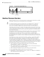
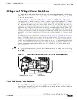
Figure 2-5
20A AC-Input Power Cable Connector, Plug, and Receptacle (Cisco 7513,
Cisco 7513-MX, and Cisco 7576)
The DC-powered chassis requires a minimum 35A dedicated service (at –48 VDC). We recommend that
you use an 8-AWG, highly flexible stranded cable for the DC power connections.
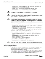
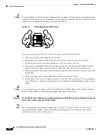
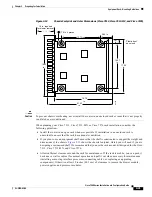
Figure 2-6
shows the
conductor preparations.
Figure 2-6
DC-Input Power Cable Connection to Terminal Block (Cisco 7513, Cisco 7513-MX, and
Cisco 7576)
Plant Wiring Guidelines
This section provides guidelines for setting up the plant wiring and cabling at your site. When planning
the location of the new system, consider wiring issues, distance limitations for signaling,
electromagnetic interference, and connector compatibility, as described in the sections that follow.
Interference Considerations with Cabling
When wires are run for any significant distance in an electromagnetic field, interference can occur
between the field and the signals on the wires. This fact has two implications for the construction of plant
wiring:
•
Bad practices can result in radio interference emanating from the plant wiring.
•
Strong electromagnetic interference (EMI), especially as caused by lightning or radio transmitters,
can destroy the signal drivers and receivers in the router, and can even create an electrical hazard by
conducting power surges through lines and into equipment. (Review the safety warnings in the
“Safety Recommendations” section on page 2-2
.)
H3164
IEC 320 20-amp connector
(to the AC power supply)
20-amp plug
20-amp receptacle
8-AWG conductor
Crimp area
Maximum exposed
conductor surface
H3814
.610
.210
.925
.39
.140
.83
End View
All measurements in inches


