


6-4
Cisco 7500 Series Installation and Configuration Guide
OL-5008-03 B0
Chapter 6 Maintaining Your Cisco 7507 and Cisco 7507-MX Router
Maintenance Procedures for the Cisco 7507 and Cisco 7507-MX
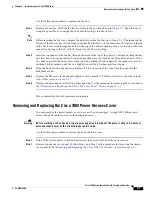
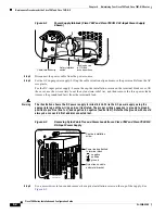
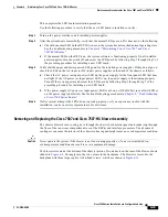
Figure 6-1
Power Supply Interlock (Cisco 7507 and Cisco 7507-MX AC-Input Power Supply
Shown)
Step 3
Disconnect the power cable from the power source.
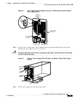
Step 4
For the AC-input power supply: Lift up the cable retention clip and remove the power cable from the AC
receptacle.
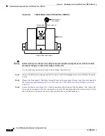
For the DC-input power supply: Loosen the captive installation screws on the terminal block cover, lift
the cover, use the wire cutters to cut the nylon strain-relief ties, and then remove the three power leads
(remove the ground lead last) from the terminal block.
Warning
The illustration shows the DC power supply terminal block. Wire the DC power supply using the
appropriate lugs at the wiring end, as illustrated. The proper wiring sequence is ground to ground,
positive to positive (line to L), and negative to negative (neutral to N). Note that the ground wire should
always be connected first and disconnected last.
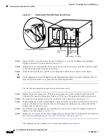
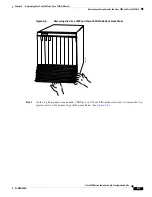
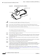
Figure 6-2
Removing Nylon Cable Ties and Power Leads from a Cisco 7507 and Cisco 7507-MX
DC-Input Power Supply
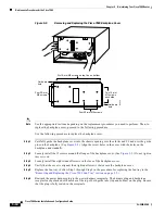
Step 5
Use a screwdriver to loosen and remove the captive installation screw on the top of the supply. See
Figure 6-3
.
Safety interlock
switch
Locking device
in ON and
locked positions
I
O
H1315a
Cable-retention clip
OUT FAIL
INPUT POWER
DO NOT SHIP WITH POWER SUPPLY
INSTALLED
FASTENER TO BE FULLY ENGAGED
BEFORE OPERATING POWER SUPPLY
INPUT VOLTAGE : 40-72 V=
INPUT CURRENT : 24-13A
Captive installation
screw
Power leads attached
to terminal block
( ) negative
( ) positive
( ) ground
H2530
Nylon ties on cable
and metal bracket