


6-3
Cisco 7500 Series Installation and Configuration Guide
OL-5008-03 B0
Chapter 6 Maintaining Your Cisco 7507 and Cisco 7507-MX Router
Maintenance Procedures for the Cisco 7507 and Cisco 7507-MX
Maintenance Procedures for the Cisco 7507 and
Cisco 7507-MX
The specific maintenance procedures for your Cisco 7507 or Cisco 7507-MX router are described in the
following sections:
•
Removing Cisco 7507 and Cisco 7507-MX Power Supplies, page 6-3
To install power supplies in the Cisco 7507 or Cisco 7507-MX, see the
“Installing Cisco 7507 and
Cisco 7507-MX Power Supplies” section on page 3-14
.
•
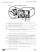
Removing and Replacing the Cisco 7507 and Cisco 7507-MX Front Chassis Panels, page 6-6
•
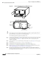
Cleaning and Replacing the Cisco 7507 and Cisco 7507-MX Air Filter, page 6-10
•
Replacing Cisco 7507 and Cisco 7507-MX Internal Components, page 6-11
Warning
Before working on a system that has an on/off switch, turn OFF the power and unplug the power cord.
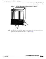
Removing Cisco 7507 and Cisco 7507-MX Power Supplies
This section describes the procedure for removing power supplies from the Cisco 7507 and Cisco
7507-MX.
Note
The procedure for installing power supplies in the Cisco 7507 and Cisco 7507-MX is included in the
“Installing Cisco 7507 and Cisco 7507-MX Power Supplies” section on page 3-14
.
Redundant power supplies support online insertion and removal (OIR); if you remove one power supply,
the second supply immediately ramps up to supply full power to the system to maintain uninterrupted
operation.
If you have only one power supply in your Cisco 7507 or Cisco 7507-MX, you must turn off power
before removing and replacing it. Always install a filler plate over an empty power supply bay to protect
the connectors from contamination.
Warning
When stranded wiring is required, use approved wiring terminations, such as closed-loop or
spade-type with upturned lugs. These terminations should be the appropriate size for the wires and
should clamp both the insulation and the conductor.
Warning
Before performing any of the following procedures, ensure that power is removed from the DC circuit.
To ensure that all power is OFF, locate the circuit breaker on the panel board that services the DC
circuit, switch the circuit breaker to the OFF position, and tape the switch handle of the circuit
breaker in the OFF position.
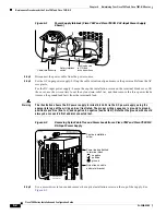
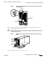
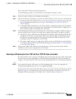
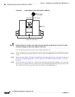
Use the following procedure to remove a power supply:
Step 1
If you are replacing the DC-input power supply, turn off the power supply DC power source.
Step 2
On the power supply to be removed, turn off the switch. The interlock tab will retract into the unit.