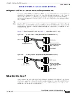
R E V I E W D R A F T — C I S C O C O N F I D E N T I A L
3-23
Cisco 7500 Series Installation and Configuration Guide
OL-5008-03 B0
Chapter 3 Installing a Cisco 7500 Series Router
Installing the Cisco 7513, Cisco 7513-MX, and Cisco 7576
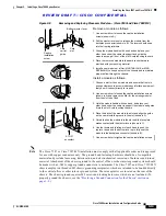
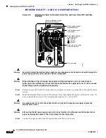
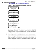
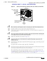
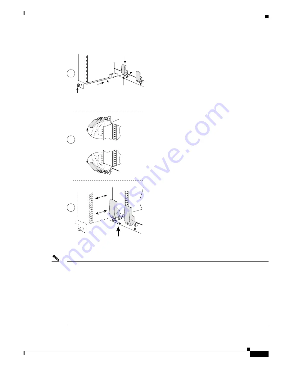
Figure 3-14
Removing and Replacing Processor Modules (*Cisco 7513, Cisco 7513-MX, and
Cisco 7576)
Note
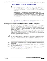
Wiring codes prevent 20A plugs from being used with most equipment rack power strips. A Cisco 7513,
Cisco 7513-MX, or Cisco 7576 installation must comply with all applicable codes and is approved for
use with copper conductors only. The ground bond fastening hardware should be of compatible material
and preclude loosening, deterioration, and electrochemical corrosion of hardware and joined material.
Attachment of the chassis ground receptacles to the central office or other interior ground system should
be made with a 6-AWG, copper ground conductor at a minimum. The Cisco 7513, Cisco 7513-MX, and
Cisco 7576 chassis employ two threaded M5 chassis grounding receptacles. These receptacles are
intended to be bonded directly to the central office or other interior ground system, and are located on
the rear of the chassis. The chassis grounding receptacles require M5 screws and locking hardware,
which are not included. (To properly ground the chassis, see the
“Providing a Ground Connection for the
Chassis” section on page 3-2
.)
122304
STOP!
on contact
Bottom ejector lever
Captive
installation
screw
Card
carrier
guide
A
B
C
Remove a module as follows:
1. Use a screwdriver to loosen the captive installation
screws (shown in A).
2. Pull the ejector levers out to release the module from the
backplane connector (shown in B). The levers should snap
into their spring retainers.
3. Grasp the module handle with one hand and place your
other hand under the carrier to support and guide the
module as you pull it out of the slot. Avoid touching the card.
4. Place the removed module in the board racks that were
provided with your packing material.
5. Install a new module or a filler (MAS-7KBLANK or MAS-
RSPBLANK) to keep dust out of the chassis and to maintain
proper airflow through the chassis.
Install a module as follows:
1. Choose a slot for the new module and ensure that there is
enough clearance to accommodate any interface equipment
that you will connect directly to its ports.
2. Use a screwdriver to loosen the captive installation screws
(shown in A) and remove the filler (or the existing module)
from the slot to be filled.
3. Hold the module handle with one hand, and place your
other hand under the carrier to support the module and guide
it into the slot. Avoid touching the card.
4. Place the back of the module in the slot and align the guide
on the carrier with the groove in the slot (shown in A).
5. Carefully slide the module into the slot until the faceplate
makes contact with the ejector levers (shown in C).
6. Use the thumb and forefinger of each hand to push the
top lever down and the bottom lever up to fully seat the
module in the backplane connector (shown in B).
7. Use a screwdriver to tighten the captive installation screws.
Card
slot

