5-11
Cisco 7500 Series Installation and Configuration Guide
OL-5008-03 B0
Chapter 5 Maintaining Your Cisco 7505 Router
Maintenance Procedures for the Cisco 7505
Step 7
Replace the power harness cover. (Follow Step 1 through Step 5 in the procedure for replacing the power
harness cover in the
“Removing and Replacing the Cisco 7505 Power Harness Cover” section on
page 5-7
.)
Step 8
Replace the cover panel. (Follow Step 1 through Step 4 in the procedure for replacing the cover panel in
the
“Removing and Replacing the Cisco 7505 Cover Panel” section on page 5-3
.)
This completes the Cisco 7505 backplane cover removal and replacement procedure.
Removing and Replacing the Chassis Interface in the Cisco 7505
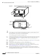
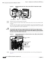
The chassis interface (CI) (shown in
Figure 5-6
) is a printed circuit board mounted to the noninterface
processor side of the backplane, behind the backplane cover. On the back (backplane side) of the chassis
are four standoffs and a connector that plugs directly into the backplane. (A spare chassis interface ships
as Product Number MAS-7500CI=.)
Figure 5-6
7500 Series Chassis Interface
When the backplane cover is in place, four standoff screws extend through the backplane cover, through
each corner of the CI and into the standoffs to keep both the CI and backplane cover in place.
This procedure assumes that you have already removed the chassis cover panel, the fan tray, the power
harness cover, the power harness, and the backplane cover. If not, see the appropriate procedures in this
section to remove these items. Replace the CI only if it fails.
Use the following procedure to remove the CI:
Step 1
Turn off the system power switch and disconnect the power cable from the power source.
Step 2
Attach an ESD-preventive strap (your own or the one supplied with the FRU) between you and an
unpainted chassis surface.
Step 3
Because you already had to remove the CI standoff screws to remove the backplane cover, the CI is held
in place only by the connector that is connected to the backplane. Grasp the edges of the CI and pull it
straight out to disconnect the CI connector from the backplane socket. (See
Figure 5-7
.)
Note
If necessary, gently rock the CI from side to side very slightly to dislodge the pins from the backplane
connector.
H2877
Chassis interface
Standoff
screw holes
Standoff
screw holes

