background image

38

Raption 150 Series Installation Manual

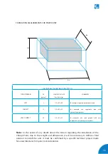
Concrete basement 
dimensions for Power Unit

J

0

1920

0

2100

Содержание Raption 150 Series

Страница 1: ...Installation Manual Raption 150 Series ...

Страница 2: ......

Страница 3: ... this manual can be reproduced copied translated or transmitted in any form or by any means without the prior written permission of the original manufacturer Information provided in this manual is intended to be accurate and reliable However the original manufacturer assumes no responsibility for its use or for any infringements upon the rights of third parties that may result from its use All oth...

Страница 4: ......

Страница 5: ...D EVSE Classification 09 E Storage 10 F Unloading and handling 11 3 Dimensions and overview 12 A Dimensions of dispenser 12 B Overview of dispenser 13 C Dimensions of power unit 14 D Overview of power unit 15 E Opening 18 F Placing 20 4 Installation 26 A Minimum distances of power unit 26 B Minimum distances of dispenser 27 Here s your guide to install Raption 150 ...

Страница 6: ... Concrete basement for dispenser 32 G Foundation template for power unit 35 H Power unit template dimensions 36 I Concrete basement for power unit 37 J Concrete basement dimensions for power unit 38 5 Wiring 40 A Power unit 42 B Dispenser 48 6 Last steps 56 A Verification 56 B How to use and configure 57 7 Technical data 58 8 Need help 62 ...

Страница 7: ...03 ...

Страница 8: ...CONTROL is not responsible for events arising from such breach ELECTRIC RISK This symbol indicates a potentially hazardous situation which if not avoided may result in a risk of fire serious injury or death The Charge Point must be disconnected from any power source before performing any maintenance repair or electrical manipulation inside ATTENTION Follow the instructions preceded by this symbol ...

Страница 9: ...2196 Plugs sockets outlets vehicle connectors and vehicles inlets Conductive charging of electric vehicles IEC 62196 1 IEC 62196 2 and IEC 62196 3 Compliant with CHAdeMO certification Meets the CCS specification DIN 70121 RFID complies with ISO IEC14443A B MIFARE Classic DESFire EV1 ISO 18092 ECMA 340 NFC 13 56MHz ISO 15118 Ready ...

Страница 10: ...IRCONTROL will reject all responsibility and the warranty will be void Comply strictly with electrical safety regulations according to your country Do not make repairs or manipulations with the unit energized Only trained and qualified personnel should have access to the electrical parts inside the Charge Point Check the installation annually by qualified technician Follow Service Manual Instructi...

Страница 11: ...cable cross section can be necessary The installation company will be responsible for dimensioning the wires cross section and the electrical protections taking into account the conditions above 3 MAX I MUM POWER OUTPUT Depending on the input power line you can carry out the charging sessions to the electric vehicle with different power output level it is possible to limit the maximum output power...

Страница 12: ... plugged in be sure hands are dry and when possible wear nonconductive gloves protective clothes and shoes with insulated soles If it is safe to do so work with only one hand keeping the other hand at your side or in your pocket away from all conductive material This precaution reduces the likelihood of accidents that result in current passing through the chest cavity Never handle electrical equip...

Страница 13: ...ermanently connected 2 Power supply Output DC EV supply equipment 3 Environmental conditions Indoor and outdoor 4 Access Equipment for locations with restricted access and Equipment for locations with non restricted access 5 Mounting method Stationary equipment Ground mounted floor mounted 6 Protection against electric shock Class II 7 Charging models Mode 4 ...

Страница 14: ...ive elements such as heat radiation direct solar radiation mechanical damage organic dissolvent impacts etc Temperature for temperatures below 20 ºC and over 60º C special attention must be paid to the storage and handling Environment Charge Point must be stored in a dry and dust free location The distance from a heat source must be 1 m away Outdoor storage of the unit has to be avoided E Storage ...

Страница 15: ...s of support Important notes The delivery truck only unloads the pallet carrying the Charge Point The delivery truck does not have the lifting facilities to move the Charge Point to its final location The placement of the Charge Point to its final location is the responsibility of the contractor Once the Charge Point is already unloaded from the truck move it to its final location with a fork lift...

Страница 16: ...12 Raption 150 Series Installation Manual 3 A Dimensions of the Dispenser Units specified in millimeters 298 380 470 1867 ...

Страница 17: ...er Depending of the model the components can vary 1 5 4 6 8 7 3 10 9 11 2 12 1 Cover 2 Courtesy Lights 3 Screen 4 CCS CHA plug 5 Emergency button 6 RFID Reader 7 Locking handle 8 Front panel 9 Antenna 10 CCS CHA cables 11 LED beacons Light 12 Front Door ...

Страница 18: ...14 Raption 150 Series Installation Manual C Dimensions of the Power Unit Units specified in millimeters 2150 800 2100 1000 ...

Страница 19: ...15 D Overview of the Power Unit 1 Cover 2 Unit air inlet 3 Locking handle 4 Locking handle 5 Rear door 6 Rear panel 7 Eyebolts 8 Unit air outlet 9 Front door 10 Front panel 3 7 8 4 1 2 5 10 9 6 ...

Страница 20: ...16 Raption 150 Series Installation Manual Power Unit front door Power input supply ...

Страница 21: ...17 Power Unit rear door Output wiring to Dispenser ...

Страница 22: ... 150 Series Installation Manual E Opening Steps 1 Insert the key supplied in the lock and turn it 90 counterclockwise 2 Pull back the handle 3 Turn the handle 90 clockwise direction Step 2 Step 3 Step 1 Dispenser ...

Страница 23: ...19 Step 2 Step 3 Step 1 Steps 1 Insert the key supplied in the lock and turn it 90 counterclockwise 2 Pull back the handle 3 Turn the handle 90 clockwise direction Power unit ...

Страница 24: ... The Charge Point is mounted on a pallet so as to do a safe transport It has to be removed before to be installed Locate the screws that are keeping the Dispenser in the pallet Remove the screws with a 17 mm spanner tool In order to place the Charge Point in its final place please follow next steps ...

Страница 25: ...llowing the next steps Steps 1 Remove the screws from the Decorative front panel on both sides and pull it outwards 2 Once the Decorative front panel is removed locate the screws that are keeping the pallet Remove the screws with a 17 mm spanner tool 1 2 ...

Страница 26: ...e the steel nerve for the eyebolt installation 4 Hold the sling to the eyebolt Make sure that it is properly fastened Raise up move and place the Dispenser in the final location Remove the eyebolt and install the roof cover when installation has been finished It is mandatory to remove the roof cover to install the eyebolt in the top of the Dispenser In like manner eyebolt has to be removed in orde...

Страница 27: ...23 1 2 3 4 ...

Страница 28: ...t the eyebolts provided are strongly tight 2 Hold the sling to the eyebolts raise the Power Point up and place it on the final location 600mm PLACI N G T H E P O WER UNIT IN THE FINAL LOC ATION Once the Power Unit is free from the pallet there are two options to move the charger Follow the next steps ...

Страница 29: ...t will be available enough space to introduce the forklift 560 mm Steps to move with forklift 1 Remove the decorative rear panel Pull outward the metal flange on both sides 2 Move out the metal flange on both sides and remove the decorative rear panel ...

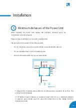
Страница 30: ... minimum lateral distance to allow proper circulation of air flow This unit has forced ventilation If Bollard Impact Protector is installed keep 500 mm as a minimum distance in order to give enough space to open the frontal door of the Charge Point for maintenance tasks 200mm 500mm 200mm 200mm ...

Страница 31: ...ll near areas where water or fluids can penetrate into the unit Do not install the Power Unit on unstable terrain Note that frontal and left side have air outlet inlets Respect the minimum lateral distance to allow proper circulation of air flow This unit has forced ventilation If Bollard Impact Protector is installed keep 1200 mm as a minimum distance in order to give enough space to open the fro...

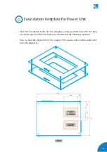
Страница 32: ...echnical definition and basic requirements for implement the base and fixing the Charge Point The unit can be installed both inside and outside Two foundation kits with a mounting templates is provided to ensure the distances between the foundation bolts Washers M16 1x 1x 16x Foundation rod 350 mm x M10 16x 4x Nuts M10 Washers M10 16x Template for Power Cabinet ...

Страница 33: ...Place the foundation bolts into the templates using provided nuts with the help of a 24mm open end wrench Take into consideration the measures of the following chapters D Foundation template for dispenser ...

Страница 34: ...30 Raption 150 Series Installation Manual E Dispenser template dimensions 435 300 70 ...

Страница 35: ...31 400 165 280 310 ...

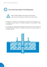
Страница 36: ...th is recommended to make a concrete base The concrete base shall provide the passage of power cables it must be done by corrugated tube placed inside the foundation through the mounting template as it can be seen below Before fixing the template inside of the croncrete basement make sure front mark must face with the front side of the charger F Concrete basement for Dispenser ...

Страница 37: ...33 0 1920 ...

Страница 38: ... x 65 For example vegetal not compact terrain COMPACT 12 55 x 55 x 55 For example mix vegetable land with engraved compactors VERY COMPACT 20 55 x 50 x 50 For example mix sand ground with very compacted and paved gravel asphalt VERY COMPACT AND CONCRETE SLAB 20 55 x 45 x 40 Minimum slab edge 10cm of concrete HM 100 FOUNDATION MEASUREMENTS FOR DISPENSER Hz Az Bz ...

Страница 39: ... provided nuts with the help of a 24mm open end wrench Take into consideration the following measures Take in mind the disposition of the supply of the power unit and the cables that go to the dispenser BACK FRONT DC OUTPUT CABLES TO DISPENSER AC CABLES IN FROM GRID 137 196 84 950 750 296 67 ...

Страница 40: ...36 Raption 150 Series Installation Manual H Power Unit template dimensions 250 350 50 50 850 714 ...

Страница 41: ...les it must be done by corrugated tube placed inside the foundation through the mounting template as it can be seen below Take into account that the supply of the Power Unit comes from the rear door The wiring that connects the Power Unit with the Dispenser can be accessed from the front door Keep this in mind when installing the metal plate Before fixing the template inside of the croncrete basem...

Страница 42: ...38 Raption 150 Series Installation Manual Concrete basement dimensions for Power Unit J 0 2100 ...

Страница 43: ...RY COMPACT 20 110 x 95 x 35 For example mix sand ground with very compacted and paved gravel asphalt Hz Az Bz FOUNDATION MEASUREMENTS FOR POWER UNIT Note In the event of any doubt about the terrain regarding the installation of the Charge Point due to the weight and dimensions it will be necessary to define a final solution to install the unit It must be confirmed by a specific technical project m...

Страница 44: ...ivity of the protections has to be guaranteed at all times The proper earthing system must be TT or TN S The ground loop impedance measurement for the entire installation must be less than 80 ohms The earth resistance of the charging point could be less if required by national regulations It is recommended to maintain these conditions over the years therefore technically competent personnel will c...

Страница 45: ... power unit and dispenser is 30m N L1 L2 L3 PE PE DC 2 L N PE ETHERNET CABLE 2 1 3 DC 1 2 DC 1 CHA power cables DC 2 CCS power cables PE earth cable for the Dispenser L N PE supply for the Dispenser electronics Ethernet Cable For communications between Power Unit and Dispenser ...

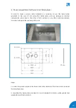
Страница 46: ...ng this metal plate and any damage to internal components arises due to the entry of dirt animals or any other external element Circontrol will reject the warranty of the unit Steps 1 Locate the power input entrance in the bottom of the Power Unit Accessed from the back door 2 Remove the metal plate 2 Assembly the metal plate provided It is recommended to install a cable glands not supplied Power ...

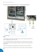
Страница 47: ...43 2 Power connection for the Power Unit Scheme Power cabinet must be supplied with 1 Three phases Neutral 230 400V 50Hz 2 Earth cable ...

Страница 48: ...ightening torque has to be 13Nm 2 Use a M8 metallic electric terminal aligned with the required cable cross section according with the power of the Charge Point Max 150 mm2 See this requirement in the data sheet 3 After connecting the power supply place the sheet protection over the circuit breaker 4 Keep in mind the earth connection Earth cable to Dispenser must be taken from here PE PE to the di...

Страница 49: ... and any damage to internal components arises due to the entry of dirt animals or any other external element Circontrol will reject the warranty of the unit Steps 1 Locate the power output in the Power Unit in the bottom of the Power Unit Accessed from the front door 2 Assembly the metal plate provided It is recommended to install a cable glands not supplied in pre holes position ...

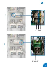
Страница 50: ...46 Raption 150 Series Installation Manual 5 Power output connection from Power Unit Connecting Cables Locate the connection points in the Power Unit ETHERNET L1 N PE 1 2 2 1 3 ...

Страница 51: ...47 CCS CCS CHA CHA 3 ...

Страница 52: ...order to make a secure cable installation is necessary to use the metal plate provided In the case of not using this metal plate and any damage to internal components arises due to the entry of dirt animals or any other external element Circontrol will reject the warranty of the unit Dispenser B ...

Страница 53: ...49 PE DC 2 L N PE ETHERNET CABLE 2 1 3 DC 1 2 2 Wiring connection for the Dispenser Scheme ...

Страница 54: ...50 Raption 150 Series Installation Manual 3 Power input connection to Dispenser connecting cables Locate the connection points in the Dispenser 1 2 3 ...

Страница 55: ...51 L1 N PE ETHERNET 1 2 ...

Страница 56: ...52 Raption 150 Series Installation Manual CCS CCS 3 ...

Страница 57: ...53 CHA PE CHA 3 ...

Страница 58: ... if the installation method is another one at any case it has to be calculated by the installer taking into account the cable materials the conditions of installation and distances Take into consideration the distance between the power unit and the dispenser It affects the final cross sectional area to be used This is the maximum cable cross sectional area accepted by the Main circuit breaker Note...

Страница 59: ...55 ...

Страница 60: ...s are correctly placed Close the Charge Point s doors The Charge Point has a security switch anti tamper protection installed that will avoid any charging session if the doors are opened Check that all beacons are illuminated in green Verify that each EV connector is in good condition Make sure the ventilation air flow is correct and there is not any obstruction at the air inlets and outlets Check...

Страница 61: ...r to use and configure the Charge Point there is an Instruction Manual To get it download it from the Expert Area or send a mail to ps support circontrol com Note Ask Circontrol PS Support Department in order to register in the Circontrol Expert Area ...

Страница 62: ...AdeMO 3 4 meters Lights for status indication RGB colours indicator Dimensions D x W x H 378x420x2067mm Weight 115 kg Operational noise level Not perceptible AC Meter Compliant with the EN 50470 MID European standards or IEC 62052 11 GENERAL SPECIFICATIONS Compliance CE Combo 2 DIN 70121 ISO15118 IEC 61851 1 IEC 61851 23 CHAdeMO compatible Enclosure rating IP54 IK10 Enclosure material Stainless st...

Страница 63: ...5693 ISO 18092 Sony FeliCa Low temperature Kit 30ºC to 50ºC POWER UNIT AC power supply 3P N PE AC Voltage 400 V AC 10 Maximum AC input current 237 A Required power supply capacity 164 KVA Power Factor pu 0 98 Efficiency pu 94 at nominal output power Frequency pu 50 60 Hz Cooling system Forced air Operational noise level 55 dBA Electrical input protection Main circuit disconnection Overcurrent prot...

Страница 64: ...Maximum output power CCS 150kW CHA 62 5kW 150kW Maximum output power when charging two cars simultaneously CCS 75kW CHA 62 5kW Output voltage range CCS 100 920 VDC CHA 100 500 VDC 100 920 VDC Maximum output current 200A CCS 125A CHA 200A Number of plugs 2 1 150kW 750 920 V 80kW 400 V ...

Страница 65: ...61 ...

Страница 66: ...62 Raption 150 Series Installation Manual 8 ...

Страница 67: ...63 Need help In case of any query or need further information please contact our Post Sales Department 34 937 362 940 34 937 362 941 ps support circontrol com circontrol com ...

Страница 68: ...CIRCONTROL Raption 150 Series INSTALLATION MANUAL A comprehensive guide on how to install and verify your Raption 150 Charge Point V1 2 March edition 2020 CIRCONTROL S A ALL RIGHTS RESERVED R207 ...

Отзывы: