21
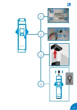
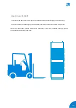
Repeat the same process with the Power Unit but following the next steps:
Steps:
1- Remove the screws from the Decorative front panel (on both sides) and pull it
outwards.
2- Once the Decorative front panel is removed, locate the screws that are keeping
the pallet. Remove the screws with a 17 mm spanner tool.
1
2
Содержание Raption 150 Series
Страница 1: ...Installation Manual Raption 150 Series ...
Страница 2: ......
Страница 4: ......
Страница 7: ...03 ...
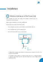
Страница 20: ...16 Raption 150 Series Installation Manual Power Unit front door Power input supply ...
Страница 21: ...17 Power Unit rear door Output wiring to Dispenser ...
Страница 27: ...23 1 2 3 4 ...
Страница 34: ...30 Raption 150 Series Installation Manual E Dispenser template dimensions 435 300 70 ...
Страница 35: ...31 400 165 280 310 ...
Страница 37: ...33 0 1920 ...
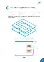
Страница 40: ...36 Raption 150 Series Installation Manual H Power Unit template dimensions 250 350 50 50 850 714 ...
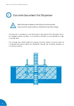
Страница 42: ...38 Raption 150 Series Installation Manual Concrete basement dimensions for Power Unit J 0 2100 ...
Страница 51: ...47 CCS CCS CHA CHA 3 ...
Страница 53: ...49 PE DC 2 L N PE ETHERNET CABLE 2 1 3 DC 1 2 2 Wiring connection for the Dispenser Scheme ...
Страница 55: ...51 L1 N PE ETHERNET 1 2 ...
Страница 56: ...52 Raption 150 Series Installation Manual CCS CCS 3 ...
Страница 57: ...53 CHA PE CHA 3 ...
Страница 59: ...55 ...
Страница 65: ...61 ...
Страница 66: ...62 Raption 150 Series Installation Manual 8 ...

