04
Raption 150 Series Installation Manual
This manual provides information for installing the Charge Point, which has been
designed and tested to allow charging electric vehicles, as specified at IEC 61851
standards.
This document has different sections describing electrical components inside the
Charge Point and a step-by-step installation procedure.
It is mandatory to follow the basic security information supplied in this manual to
ensure safe and proper installation.
Failure to follow safety instructions may involve personal injury, equipment damage
and danger of death. CIRCONTROL is not responsible for events arising from such
breach.
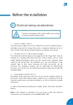
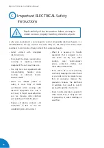
ELECTRIC RISK
- This symbol indicates a potentially hazardous situation which, if not
avoided may result in a risk of fire, serious injury or death.
- The Charge Point must be disconnected from any power source before
performing any maintenance, repair or electrical manipulation inside.
ATTENTION!
- Follow the instructions preceded by this symbol, if not respect them
or perform them correctly, may result in minor or moderate injury to
the user, damage to equipment, damage to facilities or other property.
- Handling the equipment can cause injuries as result of the dimension
and weight. Persons handling the unit must wear safety shoes and
gloves.
1
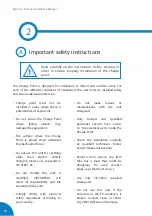
THE FOLLOWING SYMBOLS ARE USED FOR IMPORTANT
SAFETY INFORMATION IN THIS DOCUMENT
Содержание Raption 150 Series
Страница 1: ...Installation Manual Raption 150 Series ...
Страница 2: ......
Страница 4: ......
Страница 7: ...03 ...
Страница 20: ...16 Raption 150 Series Installation Manual Power Unit front door Power input supply ...
Страница 21: ...17 Power Unit rear door Output wiring to Dispenser ...
Страница 27: ...23 1 2 3 4 ...
Страница 34: ...30 Raption 150 Series Installation Manual E Dispenser template dimensions 435 300 70 ...
Страница 35: ...31 400 165 280 310 ...
Страница 37: ...33 0 1920 ...
Страница 40: ...36 Raption 150 Series Installation Manual H Power Unit template dimensions 250 350 50 50 850 714 ...
Страница 42: ...38 Raption 150 Series Installation Manual Concrete basement dimensions for Power Unit J 0 2100 ...
Страница 51: ...47 CCS CCS CHA CHA 3 ...
Страница 53: ...49 PE DC 2 L N PE ETHERNET CABLE 2 1 3 DC 1 2 2 Wiring connection for the Dispenser Scheme ...
Страница 55: ...51 L1 N PE ETHERNET 1 2 ...
Страница 56: ...52 Raption 150 Series Installation Manual CCS CCS 3 ...
Страница 57: ...53 CHA PE CHA 3 ...
Страница 59: ...55 ...
Страница 65: ...61 ...
Страница 66: ...62 Raption 150 Series Installation Manual 8 ...


