


6.1 Schedule of Function Parameters
6.1 Schedule of Function Parameters
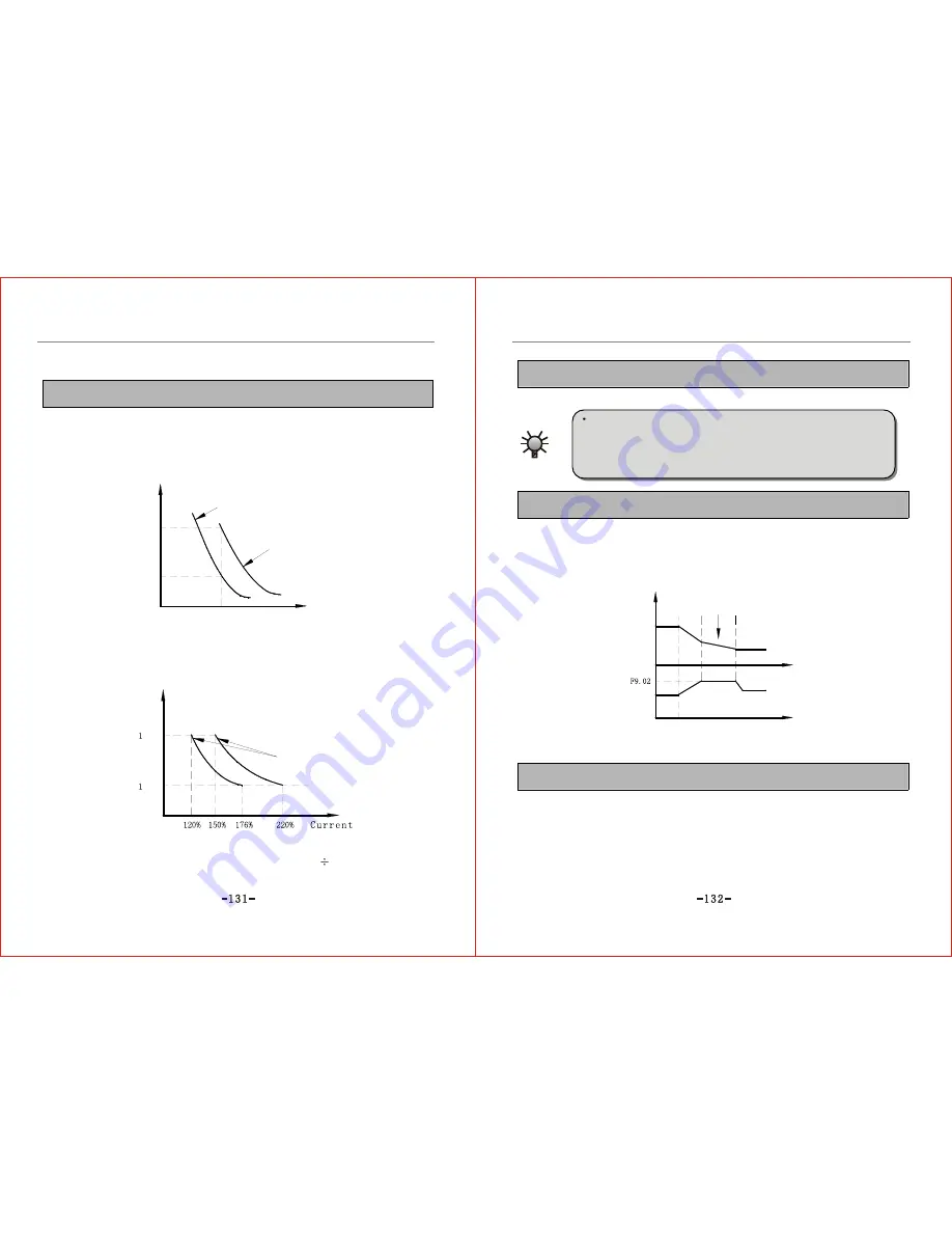
Group F9 Protection Parameters
F9.00 motor overload protection coefficient Setting range: 30~110% Default value: 105%
If the inverter's driving power rate matches the motor, the motor overload protection
coefficient can be set to 100%. If the output current is smaller than or equivalent to
150% of the inverter's rated current at this time, then motor protection is not
validated, because inverter's overload protection precedes over action, as shown in
Fig.6-30.
Time
Time
Inverter overload protection curve
overload protection curve
overload protection curve
Fig.6-30 Inverter Overload Protection Curve and Motor Overload Protection Curve
If the inverter capacity is larger than the motor capacity, to perform effective overload
protection of load motors with different specifications, it is necessary to set proper
overload protection coefficient for each type of motor and restrict the maximum current
value within the allowable output range of the inverter, as shown in Fig.6-31.
Fig.6-31 Motor Overload Protection Coefficient Setting
The formula for motor protection coefficient is shown below:
Motor overload protection coefficient=Motor rated current
Inverter rated
current x100%
F9.01 Under-voltage protection level Setting range: 180~480V Default value: As per spec.
This parameter stipulates the lower limit voltage allowed by DC bus bar when the inverter is in
normal operation.
If the grid voltage is too low, the output torque of the motor will
decrease. As for constant power rate and constant torque load, ultra-
low grid voltage will increase the inverter's input or output current.
So the inverter should be derated if it is operated at low grid voltage
for a long term.
Caution
F9.02 Over voltage protection level Setting range: 330~760 Default value: As per spec.
This parameter defines the voltage vector protection threshold of the motor during
deceleration. If DC side pump-up voltage inside the inverter excesses the value set
by this parameter, the inverter will adjust the deceleration time to delay falling or
even stop falling of output frequency. It will not perform the action of deceleration
again till the bus bar voltage is lower than the over-voltage limiting level. Shown in
Fig.6-32.
Frequency
Regulation of deceleration time
Time
Time
Fig.6-32 Over-voltage Limiting Level Declaration
F9.03 Current limiting level Setting range: 120~220% Default value: 180%
This parameter defines current limiting level. During acceleration, the inverter will
adjust its acceleration time automatically when output current of the inverter surpasses
the value stipulated by this parameter. When the current falls to this level, just
continue to accelerate to target frequency value. During constant speed operation, if
the inverter's output current exceeds the value stipulated by this parameter, the
inverter will adjust its output frequency to limit the current within the range to avoid
current trip. The default setting for this parameter is that the function of auto current
limiting is always valid during the whole process.
Содержание ZVF9V-G/P
Страница 8: ...M Integration Module S Schism Module...
Страница 12: ......
Страница 16: ......
Страница 21: ...Inverter...
Страница 33: ......
Страница 87: ......