


6.1 Schedule of Function Parameters
6.1 Schedule of Function Parameters
F5.15 Combined feed algorithm setting Setting range: 00~54 Default value: 00
This function is used to set the combined feed algorithm.
LED units digit algorithm 1 LED tens digit
Algorithm 2
0
Addition 0
Addition
1
Subtraction 1
Subtraction
2
Absolute value (subtraction) 2
Absolute value (subtraction)
3
Take the maximal value 3 Take the maximal value
4
Take the minimum value 4 Take the minimum value
5
Operating figure 3 does not participate in algorithm.
LED hundreds digit Remain
LED thousands digit Remain
Parameter F5.15 and F5.16 will be valid only when F0.01=7. Its algorithm formula
is shown below:
(Operation figure 1) Algorithm 1 (Operation figure 2) Algorithm 2 (Operation
figure 3)
If the tens digit of F5.16 is set to 5, the operation figure 3 will anticipate in
algorithm composed of two figures (operation figure 1 and operation figure 2).
Eg.1
If F5.15=534 and F5.16=10, then the algorithm pair will be:
{(AVI + digital feed 3) ACI}
Eg.2: If F5.15=460 and F5.16=21, then the algorithm pair will be:
|(Keyboard potentiometer- digital feed 2) AVI|
TIPS
Algorithm rule 1: In any case, the algorithm procedure is
always like this: operation figure 1 and operation figure 2
participate in algorithm 1 and get the result 1, then put result 1
and operation figure 3 into algorithm 2 and get the final result. If
the algorithm result of previous two figures is a negative number,
then the default result of the system will be "0".
Algorithm rule 2: If the general algorithm result is a negative
number and algorithm 2 is not an absolute one, then the default
result of the system will be "0".
Group F6 PID Function Parameters
F6.00 PID action setting Setting range: 00~11 Default value: 00
LED units digit: Function setting LED tens digit: PID input selection
0: Close 0: Auto input
1: Open 1: Hand-operated input through defined multifunction
terminals
LED hundreds digit: Remain
LED thousands digit: Remain
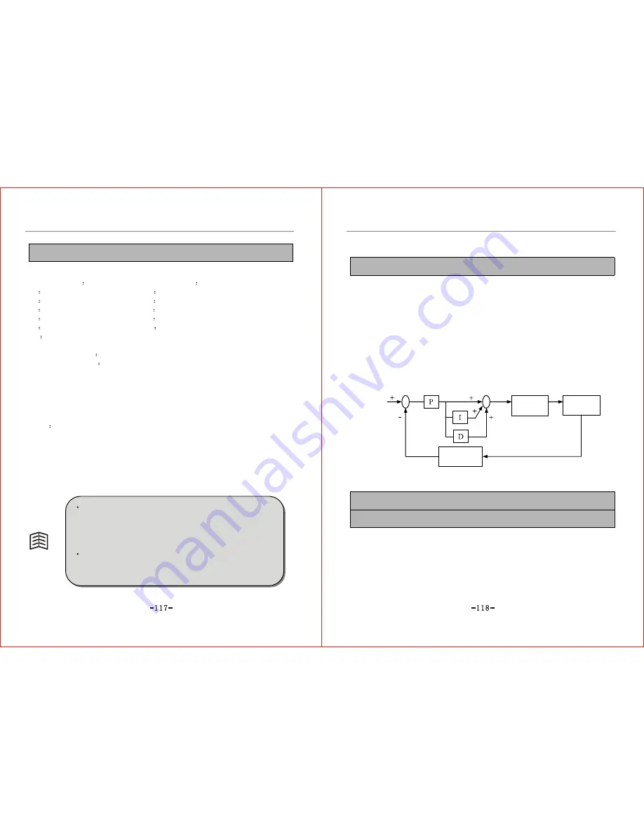
PID regulation function is described below: The built-in PID controller in the
inverter detects physical quantity (feedback quantity) through the sensor of the
object under control and compares this quantity to the target value of the system. If
deviation exists between them, then PID regulation is used to remove deviation. It
is a usual process control method used to keep the feedback quantity in accord with
the target value. This system structure is as shown in Fig. 6-21.
Target value
Output
Driving
element
Object under
control
Feedback quantity
regulation
Feedback quantity
Fig.6-17 PID Control Functional Diagram
F6.01 PID feed path selection Setting range: 0~10 Default value: 1
F6.02 PID feedback path selection Setting range: 4~10 Default value: 4
0: Keyboard potentiometer setting
To set closed-ring feed quantity by the potentiometer on the keyboard.
1: Digital quantity setting
To set the close-ring feed quantity by the target value F6.03.
2: Remain
3: Remain
Содержание ZVF9V-G/P
Страница 8: ...M Integration Module S Schism Module...
Страница 12: ......
Страница 16: ......
Страница 21: ...Inverter...
Страница 33: ......
Страница 87: ......