


6.1 Schedule of Function Parameters
6.1 Schedule of Function Parameters
F0.13 Slip frequency compensation Setting range: 0.0~150.0% Factory default setting: 0.0%
During actual rotation, a motor's slip is influenced by variation in load torque, which
causes deviation of actual speed from the expected value. With slip compensation
function, the inverter's output power can be adjusted automatically with load torque
fluctuation of the motor, which can compensate off-speed arising from load
fluctuation of the motor and thus improve accuracy of speed.
This parameter is valid if F0.01=1, as shown in Fig.6-3.
Output current
Slip compensation=100%
Before slip
compensation
After slip
compensation
Motor rotating speed
Fig.6-3 Slip Frequency Compensation Description
F0.14 Acceleration time 1 Setting range: 0.1~3600.0s Factory default setting: as per spec.
F0.15 Deceleration time 1 Setting range: 0.1~3600.0s Factory default setting: as per spec.
Acceleration time refers to the period
during which the output frequency of
the inverter is accelerated from
0.00Hz to basic frequency, as shown
in t of Fig.6-4.
1
Deceleration time refers to the period
during which the output frequency of
the inverter is decelerated from basic
frequency to 0.00Hz, as shown in t of
2
Fig. 6-4.
Fig.6-4 Diagram of
Acceleration/Deceleration Time
Output frequency
Time
This inverter series provide 4 groups of
acceleration/deceleration time parameters. Others are defined in
the parameter F2.22~F2.27 with default value of "1". Please
select other groups of acceleration/deceleration time parameters
through control terminal if other groups are preferred.
Tips
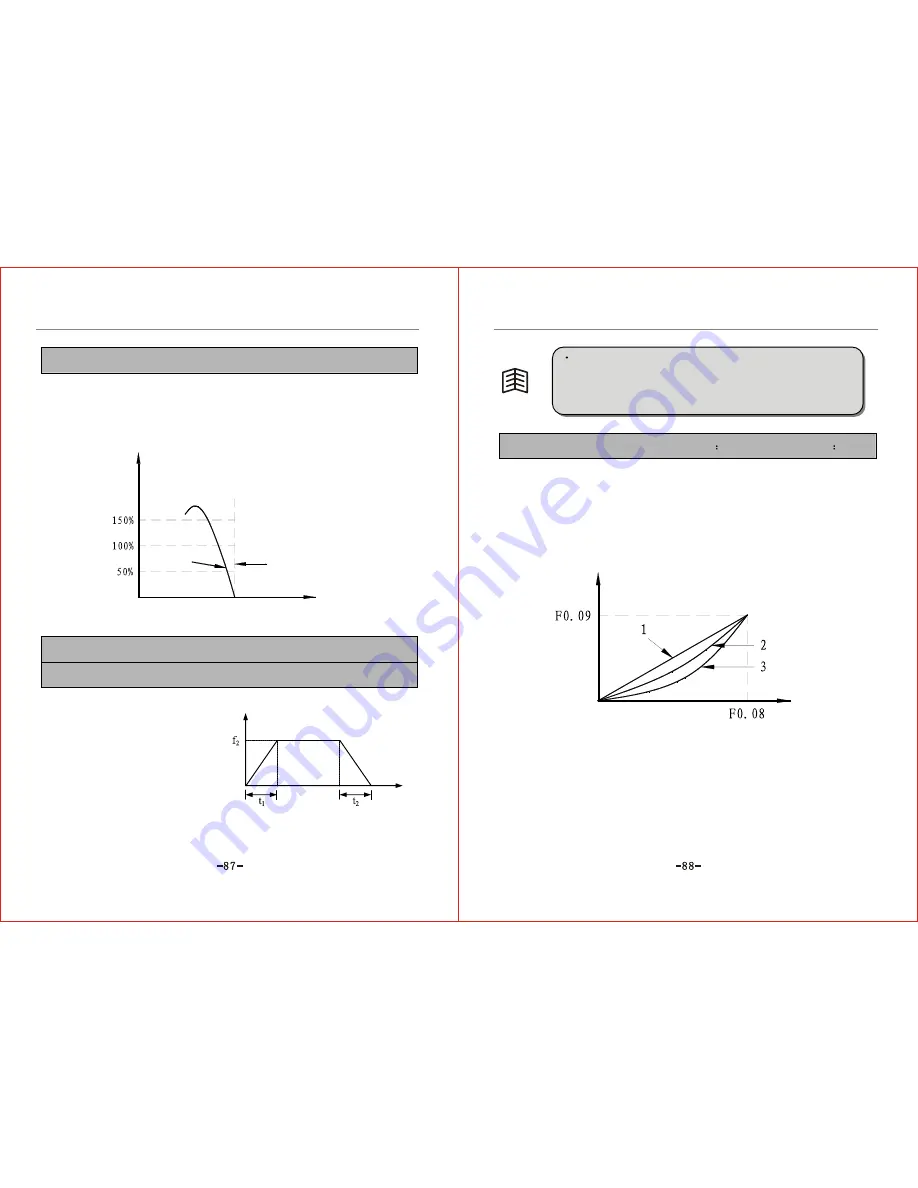
F0.16 V/F curve setting Setting range
0~3 Default setting 0
0: Constant torque
This indicates the inverter's output voltage is of positive ratio to frequency, applicable to
most loads, as shown in 1 of Fig.6-5.
1: Decreased torque curve 1
This indicates the output is a 1.7 power decreased torque curve, as shown in 2 of Fig.6-5.
2: Decreased torque curve 2
The output is the second power decreased torque curve, as shown in 3 of Fig.6-5.
Voltage
Frequency
Fig.6-5 V/F Curve
Curve 2 and 3 are applicable to fans, pumps and other variable torque loads.
Curve 3 has better effect on energy saving comparing with Curve 2. Noteworthy,
when the motor runs according to curve 2 and curve 3, unsteady operation may
occur because the motor is in a state of under excitation. Hence it is necessary to
set the curve as per detailed conditions. Or adopt a self-defined V/F curve.
3: Self-defined V/F curve
When selecting this mode, just set the expected V/F curve through F0.17~F0.22,
As shown in Fig.6-6.
Содержание ZVF9V-G/P
Страница 8: ...M Integration Module S Schism Module...
Страница 12: ......
Страница 16: ......
Страница 21: ...Inverter...
Страница 33: ......
Страница 87: ......