


6.1 Schedule of Function Parameters
6.1 Schedule of Function Parameters
28
Inverter acceleration/deceleration disable command
If this terminal is valid, the inverter will not be influenced by any external signals
(except the stop command) and remain running at current rotating speed.
29
Command shifts to terminal
If this terminal is valid, the operation command path will shift to the path of terminal
operation command forcefully, and restore to the original operation command path if it
is disconnected.
30
Frequency shifts to ACI
If this terminal is valid, the frequency feeding path will shift to ACI feeding
forcefully and restore to the original frequency feeding path if it is disconnected.
Caution
18 and 19 are valid only for multi-function terminal/port X6. The
maximum frequency of input pulse is 20KHz with low power level
of 0v and high power level of 18~26V.
F4.06 FRD/REV terminal control mode Setting range: 0~3 Default value: 0
This function is used to select four operation modes of the inverter controlled by
external terminals.
0
Two-wire control mode 1
Shown in Table 6-4 and Fig.6-13.
1
Two-wire control mode 2
Shown in Table 6-4 and Fig.6-13.
Two-wire
control 1
Two-wire
control 2
Operation
command 1
Operation
command 2
Stop
REV
FRD
Stop
Stop
Stop
FRD
REV
ig.6-9 Two-wire Control 1/2 Wiring Diagram
K2
K1
ON stands for "switching on" and OFF stands for "switchtting off".
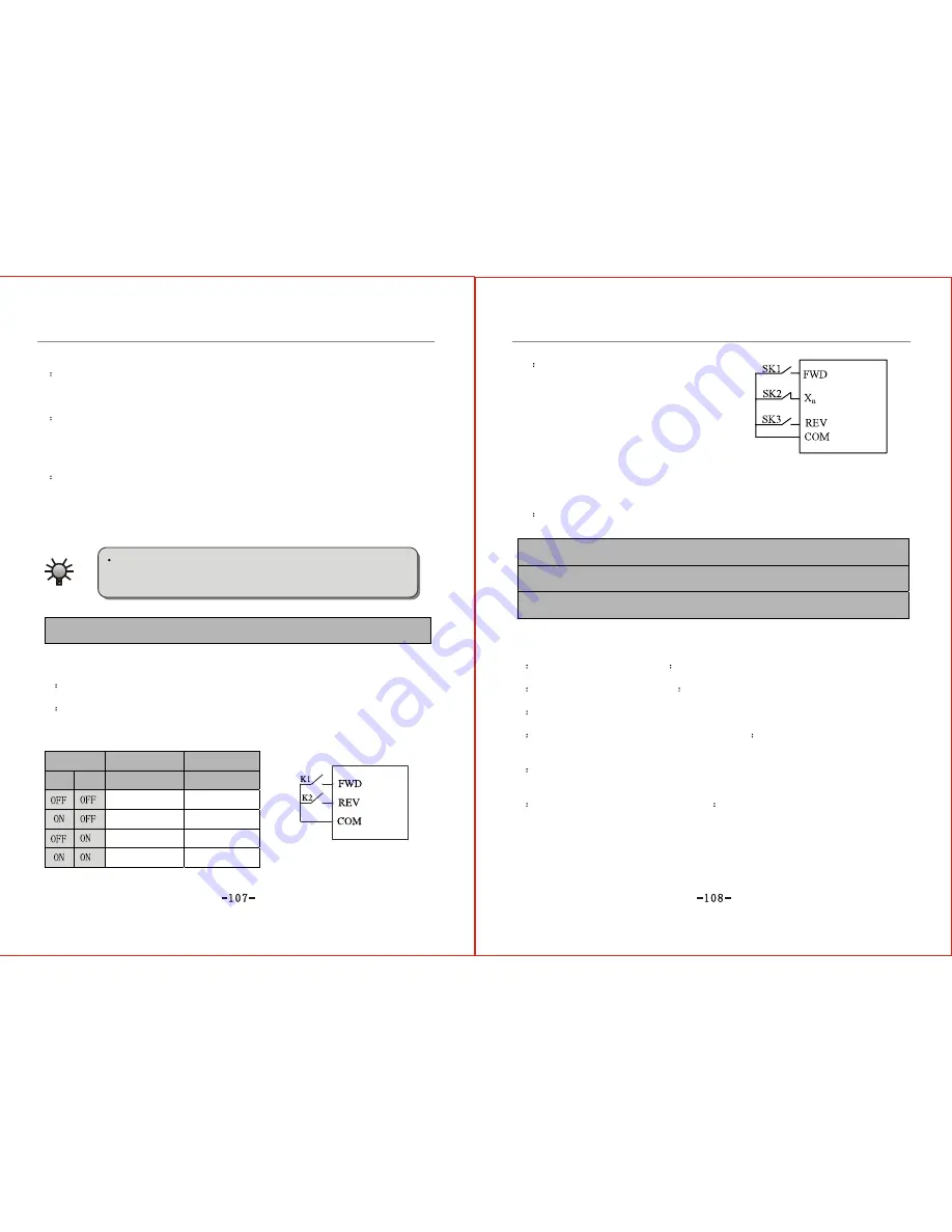
2
Three-wire control mode 1
Three-wire control is shown in Fig.6-14,
in which Xn stands for three-wire
operation control terminal which can be
any of the multi-function input terminal
X1~X6 (refer to parameter F111~F116) by
selecting "15".
SK1---FRD switch
SK2---Stop switch
SK3---REV switch
3
Three-wire control mode 2 (remain)
F4.07 Open collector output terminal Y1 setting Setting range: 0~15 Default value: 0
F4.08 Open collector output terminal Y2 setting Setting range: 0~15 Default value: 1
F4.09 Programmable relay output setting Setting range: 0~15 Default value: 12
This set of parameters defines the contents of open collector output terminal Y1 and
Y2, and the contents indicated by the relay.
0
Inverter "in operation" signal
This indicates the outlet indication signal of the inverter in the state of operation.
1
Frequency arrival (FAR) signal
Refer to the function declaration of F4.12.
2
Frequency level detection (FDT) signal:
Refer to the function declaration of F4.10.
3
Inverter null revolution "in service" instruction
This indicates the indication signal outlet by the inverter is still in the state of
operation though the output frequency of the inverter is 0.00Hz.
4
External failure stop
When failure signal of external equipment is received through input terminal, the
inverter will perform trip alarm and the terminal "Y" outlets indication signal.
5
Upper limit of output frequency arrival
This refers to the indication signal of the inverter output by the inverter when the running frequency
reaches the upper limit of frequency.
ON/OFF state
Table 6-4 Two-Wire mode control running command sheet
Fig.6-14: Three-wire control wiring diagram
Содержание ZVF9V-G/P
Страница 8: ...M Integration Module S Schism Module...
Страница 12: ......
Страница 16: ......
Страница 21: ...Inverter...
Страница 33: ......
Страница 87: ......