


6.1 Schedule of Function Parameters
6.1 Schedule of Function Parameters
4: AVI setting
To set the target value by external voltage signal AVI (0~10V).
5: ACI setting
To set the target value by external current signal I (0~20mA).
6: Terminal pulse setting
To set the target value by external pulse.
7: AVI + ACI setting
To set the target value by the
algebraic sum
of AVI + ACI.
8: AVI - ACI setting
To set the target value by the algebraic difference of AVI - ACI. If AVI
ACI, Ithe
result will always be "0".
9: Min {AVI, ACI}
To take the smaller one from AVI and ACI.
10: Min {AVI, ACI}
To take the bigger one from AVI and ACI.
TIP
Do not set the same value for the feed path and feedback path.
Otherwise, the feed quantity will be the same as the feedback
quantity without any deviation, resulting in PID's abnormal work.
Besides, do not set the feedback path within 0~3, or there will be
no meaning.
F6.03 Feed digital setting Setting range: 0.00~10.00V Default value: 0.0V
This parameter is used to set the target value (unit: V) controlled by PID when PID
target value is selected to be set by digital setting (F6.01=1).
Do take full consideration of the relationship between manometer range and its
output feedback signal when setting this parameter in a constant closed-loop water
supply system. Generally, its calculating formula is:
Feed digital quantity setting = 10.00V manometer range
required pressure value
Eg. If the manometer range is 12Mpa and required pressure setting value is 6Mpa,
then the feed digital quantity setting shall be 6.00V instead of 5.00V.
F6.04 Feedback path gain Setting range: 0.01~10.00 Default value: 1.00
If the feedback quantity is not in accord with the actual target value, then this
parameter can be used to regulate the PID value till it is in accord with the request.
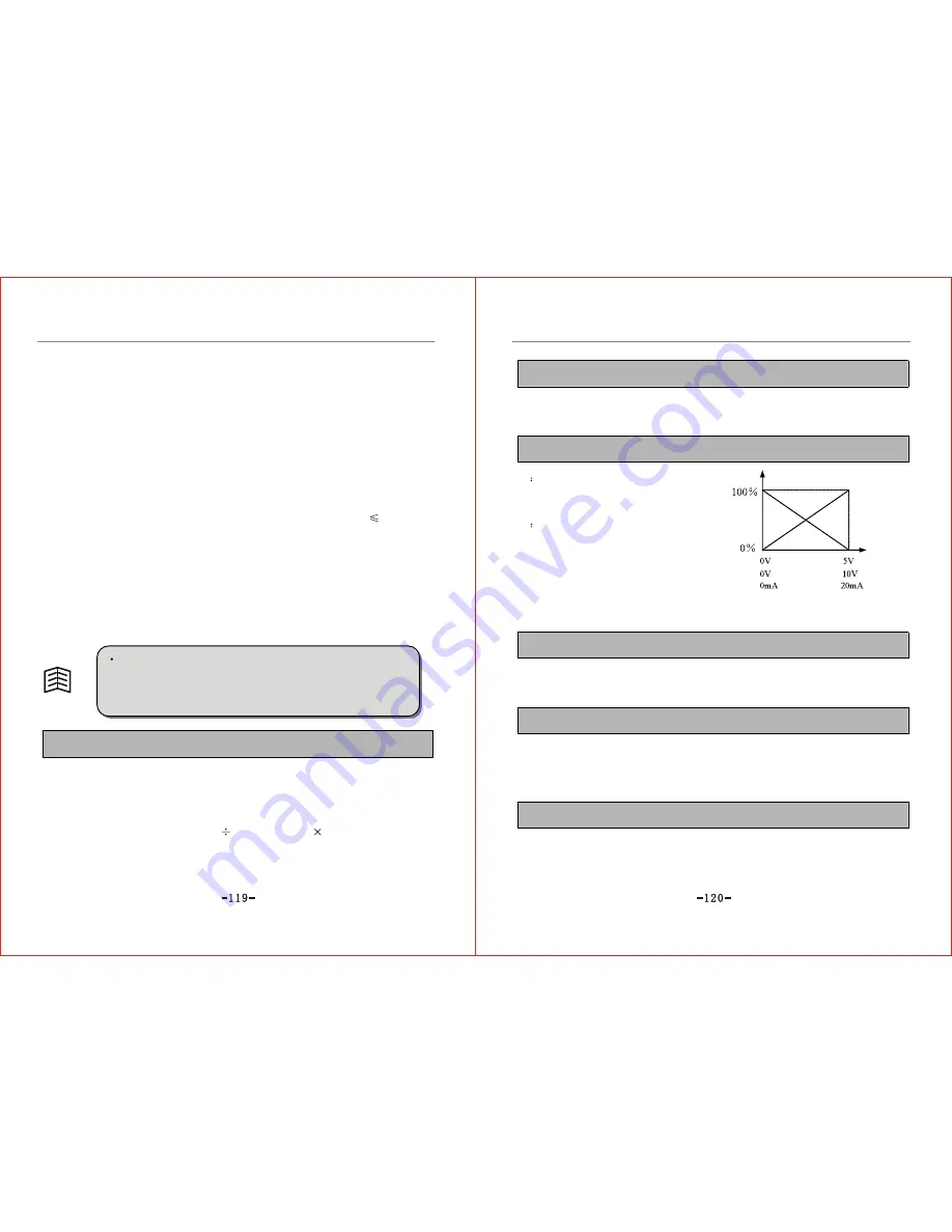
F6.05 Feedback path polarity Setting range: 0~1 Default value: 0
0
Positive:
This indicates the maximum feedback
quantity corresponding to the maximum
input signal.
1
Negative:
This indicates the maximum feedback
quantity corresponding to the minimum
input signal. Refer to Fig.6-22 for details.
Feedback quantity
Positive
Negative
Input
Fig.6-22 Diagram of Feedback
Polarity Selection
F6.06 Proportional gain P Setting range: 0.01~10.00 Default value: 1.00
Proportional gain (P) decides response degree of output frequency to deviation. The
greater the P value is, the quicker response is, but excessive value of P may result in
oscillation and too low value of P may lead to response lagging.
F6.07 Integral time constant Ti Setting range: 0.0~200.0s Default value: 10.0s
Integral time constant decides the proportional relation between output frequency change speed
and deviation. The function of integral is to integrate the output value in accordance with
deviation to compensate deviation between feedback value and set value. Too long integral time
may result in slow response to external disturbance. The shorter the constant time is, the quicker
the response speed is, but too short integral time may result in oscillation.
F6.08 Differential time constant Td Setting range: 0.0~10.0s Default value: 0.0s
The function of differential is to proportionate output frequency to deviation, and respond timely
to abruptly changing deviation. The longer the differential time is, the faster decay of system
oscillation arising from proportional action is, but too long differential time may result in
oscillation. Vise versa, the shorter the differential time is, the less decay of oscillator is. If
F6.08=0.0, differential will be invalid.
Содержание ZVF9V-G/P
Страница 8: ...M Integration Module S Schism Module...
Страница 12: ......
Страница 16: ......
Страница 21: ...Inverter...
Страница 33: ......
Страница 87: ......