


Programmable DC Power Supply 62000L Series User’s Manual
3-14
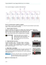
The connection diagram in parallel is illustrated below.
How to connection power supplies in parallel:
For example, to connect 3 units in parallel for to output 21A, please follow the procedures
below. There are three parts to the setup.
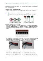
1. Control signal connection
Connect T+ (Master) to R+ (Slave1), R- (Slave1) to R+ (Slave2), and R- (Slave2) to T-
(Master). Then connect S+ (Master) to the positive side of the DUT
(Device under Test), and S- (Master) to the negative side of the
DUT. This setup concept is always used if you want to make up
other output systems with two or more 62010L-36-7s in parallel.
1. When making the series connection,
please wire the sense to your DUT to do
the necessary current compensation.
2. Each control system can use seven (7)
units at most.
2. Output terminal connection
Connect the Slave2 output - to the Slave1 output -, the Slave2
to the Slave , the Slave1 output – to the Master
output -, the Slave1 to the Master , the Master
output – to the DUT -, and the Master to the DUT + to form
the connection in parallel.
3. Master/Slave mode Setup
When the connection in parallel is used, the output current is the sum
of the currents from the connected power supplies. Each of the
individual power supplies must be properly set in order to obtain the
total output current.
The sum will not be shown on the display. You have
to calculate that yourself or include a load (or a
meter) to inspect the total output current.
●
Master Unit (Quantity X 1)
:
CAUTION
Master Unit
Slave Unit
Output Connection


