


Programmable DC Power Supply 62000L Series User’s Manual
2-4
level, and clear overcurrent condition.
9.
Menu:
This button accesses the function settings. When the Menu button is pressed, and
the knob is rotated, the display will show SENSE, MA/SL, SEQ, SYSTEM, CAL, and GPIB
one by one. This button is also used to answer “Yes”, i.e. “Confirmed” or “Applied.”
10.
Store Button:
Store an operating state at the location 0, 1, 2… or 15.
11.
Recall Button:
Recall a previously stored operating state from the location 0, 1, 2… or 15.
12.
Limit Button:
Press it to show the voltage and current limit values on the display and
allow the knob adjustment to set the limit values.
13.
Lock/Local Button:
When
pressing the
LOCK
button, the Lock annunciator on the
display is lit, and the Lock function is enabled until the same button is pressed once again.
This button can be used as the Local Key when the power supply is operating under the
remote interface mode.
14.
Output On/Off Button:
Enable or disable the power supply output. This key toggles
between on and off.
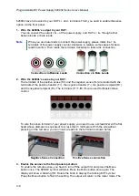
15.
Positive Terminal:
Red terminal outputs positive voltage.
16.
Negative Terminal:
Black terminal outputs negative voltage.
17.
GND Terminal:
Terminal is at earth potential. Used for measurement of control circuits
designed to be operated with one terminal at earth potential.
18.
Sensing Terminal (S+/S-):
The Remote Sensing Terminal is used to compensate for load
current dependent voltage drops.
19.
Transfer Terminal (T+/T-):
Under the Master-Slave Mode, the master unit’s T+ connects
to the first slave unit’s R+. Then its R- connects to the other unit’s R+, and so on. The last
slave unit’s R- connects to the master unit’s T-.
20.
Recipient Terminal (R+/R-):
Under the Master-Slave Mode, the master unit’s T+
connects to the first slave unit’s R+. Then its R- connects to the other unit’s R+ and so on.
The last slave unit’s R- connects to the master unit’s T-.
21.
Remote Sensing Cover:
This cover is used to protect against moisture and dust.
2.4.2 Rear Panel Overview
1.
Air Outlet:
There are four air vents for cooling purposes.
2.
USB Interface:
USB interface
3.
GPIB Interface:
Through the IEEE-488 interface, you can communicate with any PC


