Programmable DC Power Supply
62000L Series
User’s Manual
Version 1.1
October 2017
Страница 1: ......
Страница 2: ......
Страница 3: ...Programmable DC Power Supply 62000L Series User s Manual Version 1 1 October 2017...
Страница 4: ...a ATE INC shall not be held liable for errors contained herein or direct indirect special incidental or consequential damages in connection with the furnishing performance or use of this material CHRO...
Страница 5: ...or operations repairs will be billed at cost Chroma assumes no responsibility for its product being used in a hazardous or dangerous manner either alone or in conjunction with other equipment High vo...
Страница 6: ...ective 2011 65 EU indicates that the level of the specified chemical substance exceeds the threshold level specified in the standards of SJ T 11363 2006 and EU Directive 2011 65 EU Remarks The CE mark...
Страница 7: ...1 Chroma is not fully transitioned to lead free solder assembly at this moment however most of the components used are RoHS compliant 2 The environment friendly usage period of the product is assumed...
Страница 8: ...vi...
Страница 9: ...CESSITY OF PROTECTIVE GROUNDING Never cut off the internal or external protective grounding wire or disconnect the wiring of protective grounding terminal Doing so will cause a potential shock hazard...
Страница 10: ...und is not explicitly stated This symbol indicates the power connector does not provide grounding Frame or chassis To identify a frame or chassis terminal Alternating Current AC Direct Current DC Alte...
Страница 11: ...ch revision Date Version Revised Sections July 2017 1 0 Complete this manual Oct 2017 1 1 Add the entire section of Overpower Protection Modify the following sections the content in the sections of Fe...
Страница 12: ......
Страница 13: ...5 2 4 4 Display Check 2 6 3 Power Supply Operation 3 1 3 1 Constant Voltage Operation 3 2 3 2 Constant Current Operation 3 3 3 3 Storing and Recalling Operation States 3 4 3 4 Setting the Overvoltage...
Страница 14: ...I Command Terminators 4 3 4 1 7 Common SCPI Commands 4 3 4 1 8 SCPI Parameter Types 4 3 4 2 SCPI Commands 4 4 4 2 1 Output Settings and Operation Commands 4 4 4 2 2 Triggering Commands 4 8 4 2 2 1 Tri...
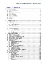
Страница 15: ...l service representative 1 1 Features Operations The 62000L series is a high performance auto ranging portable DC power supply Max 108W 36V 7A 150W 60V 6A with a single channel output and standard GPI...
Страница 16: ...ble The enhanced sensitivity completely replaces the need for numerical input keys Highly Readable Display High Accuracy and Resolution Fast Response Time The oscilloscope test below measures the time...
Страница 17: ...f a 3 5 A to 7 A load step with the recovery taking only 14 0 us Wave in Blue Voltage Wave in Purple Current Fast Response Time 2 Remote Voltage Sense without Shorting Bars Overvoltage Protection OVP...
Страница 18: ...Front Bumper The Rear Bumper Units Stacked Hidden Carrying Handle Hidden State Holding State Portable Size H 2U W 1 2U and Light Weight 2 5Kgs or 5 5Lbs The 62000L series weight is less than 2 5Kgs Th...
Страница 19: ...accuracy is subject to calibration accuracy 1 2 Precautions Please carefully read the manual before operating this device This manual is for reference only Please consult your distributor for further...
Страница 20: ...nel may perform installation and service procedures 1 5 Safety Information Please read through the following safety information before using the product Measurement Category II is for measurements per...
Страница 21: ...Symbols and Terms This symbol indicates hazards that may cause damage to the instrument or even result in personal injury This symbol indicates high voltage may be present Use extra caution before ta...
Страница 22: ...to 50 load change 30usec 30usec Temperature Coefficient4 Voltage 0 01 3mV 0 01 3mV Current 0 02 3mA 0 02 3mA Drift4 Voltage 0 02 1mV 0 02 1mV Current 0 1 1mA 0 1 1mA Programming Measurement Resolution...
Страница 23: ...aximum change in output read back per C after a 30 minute warm up 5 The accuracy specifications are gained under 1 hour warm up condition and the calibration at 25 C 6 Maximum time required for output...
Страница 24: ......
Страница 25: ...at the power supply outputs are valid and properly responding to commands from the front panel 2 2 1 Voltage Output Check Through the following steps you may check the basic voltage functions under no...
Страница 26: ...y using a 115V or 230V single phase AC power source at 50Hz to 60Hz The rear panel shows the nominal input voltage set for the power supply at the factory If need be the power line voltage setting can...
Страница 27: ...figuration the display shows a control interface 3 Brand Model Sticker Area This area shows the product manufacturer and model name 4 Navigation Wheel Rotate this knob to increase or decrease the flas...
Страница 28: ...the power supply output This key toggles between on and off 15 Positive Terminal Red terminal outputs positive voltage 16 Negative Terminal Black terminal outputs negative voltage 17 GND Terminal Ter...
Страница 29: ...Load and rated non rated current For example 1 When CV_Limit RLoad _ the power supply will be in the CV mode and its voltage will output constantly The output current is in an inversed ratio with the...
Страница 30: ...ly is in the remote interface mode 2 CAL The power supply is in the calibration mode 3 SEQ The power supply is in the sequencing mode You can set the voltage and current output value and the timing Th...
Страница 31: ...pply s output is disabled Note You can display the following condition after rebooting your power supply To show OUTPUT OFF on the display you have to select 0 through the menu operation of the path M...
Страница 32: ......
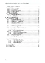
Страница 33: ...150W 62015L 60 6 For example on the 62015L 60 6 when the voltage is set to the maximum of 60V the maximum output current is 150W 60V 2 5A For a 40V setting the maximum output current is 3 75A The maxi...
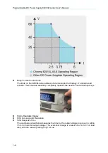
Страница 34: ...mit on the display extinguishes in 5 seconds without any operations 5 Use the knob to set the desired voltage limit Press the Limit button on the front panel and set the knob to voltage control by pre...
Страница 35: ...lashes You can change the flashing cursor using the or buttons and adjust the value to the desired current limit by turning the knob The limit setting is disabled and the Limit on the display extingui...
Страница 36: ...OVP ON OCP Level 7 7A OCP ON Voltage Limit 0V Current Limit 3A is initially saved in the locations from 0 to 15 You might use the following procedures to store and recall an operating state Note The...
Страница 37: ...e you can press any other key to exit from the present OVP settings which will not be saved in the non volatile memory Inspecting the OVP settings via the Front Panel To inspect OVP operation increase...
Страница 38: ...urn on the power supply When the power supply first turns on the output is disabled 2 To get into the OCP menu and set a desired trip level Press the OCP button once you will see the LEVEL 7 70A 6 6A...
Страница 39: ...AT OFF ON Disable or enable the OCP circuit CURR PROT CLE Clear the tripped OCP circuit 3 6 Overpower Protection Over power protection once the output power exceeds 110 of the rated power the display...
Страница 40: ...sense S are located with the terminals of the positive transfer T the negative transfer T the positive recipient R and the negative recipient R The terminals T T R R are used for Master Slave control...
Страница 41: ...on the display 3 7 3 Output Interference Any interference noise occurring on the sense leads also appears at the output of the power supply This may affect the voltage load regulation as well To minim...
Страница 42: ...uctance component of the wiring In that case the capacitor also prevents variations via output 3 Twisting the load wires is able to reduce the inductance component and stabilize the output 4 Use a cap...
Страница 43: ...means if operated in series with other power supplies damage will not occur if the load is short circuited or if one of the power supplies is turned on separately from its series partner 1 When power...
Страница 44: ...Rotate the Knob to show SETUP on the display 5 Press the Menu button to confirm 6 Rotate the Knob to show MODE on the display 7 Press the Menu button to confirm 8 Rotate the Knob to show S MA on the d...
Страница 45: ...g the output on the master unit the display on the master unit shows a voltage value and a current value On the display of the salve units only a voltage value will be shown Unit 1 set the master cond...
Страница 46: ...e wire the sense to your DUT to do the necessary current compensation 2 Each control system can use seven 7 units at most 2 Output terminal connection Connect the Slave2 output to the Slave1 output th...
Страница 47: ...Knob to show SETUP on the display 5 Press the Menu button to confirm 6 Rotate the Knob to show MODE on the display 7 Press the Menu button to confirm 8 Rotate the Knob to show P SL on the display 9 P...
Страница 48: ...the delay time are as follows 1 Press the Menu button 2 Rotate the Knob to show MA SL on the display 3 Press the Menu button to confirm 4 Rotate the Knob to show SETUP on the display 5 Press the Menu...
Страница 49: ...on to confirm 4 Rotate the Knob to show SETUP on the display 5 Press the Menu button to confirm 6 Rotate the Knob to show MODE on the display 7 Press the Menu button to confirm 8 Rotate the Knob to sh...
Страница 50: ...encing settings disable the output Note 1 Pressing the V A button long on the front panel under the SEQ mode in output condition the display will show the information of V A V W or SEQCNT V A The disp...
Страница 51: ...ing STATE To enable or disable the SEQ mode In the following example There are 3 steps used and shown on the oscilloscope The dotted lines in green divide the following waveform into 3 segments Each s...
Страница 52: ...lay Then set 0H in this setting 8 Press the Menu button once to confirm TDWELL 0M default will show on the display Then set 0M in this setting 9 Press the Menu button once to confirm TDWELL 01 000S de...
Страница 53: ...el and the source will be output sequentially Remote Operation OUTPut SEQuence STATe 0 1 OFF ON Enable Disable output sequence function OUTPut SEQuence STATe Return 0 if output sequence is disabled an...
Страница 54: ...eved in a first in first out FIFO sequence The first returned error is the first saved error When all of errors are read from the queue there will be no ERROR symbol shown on the display When more tha...
Страница 55: ...ay 5 Rotate the knob to the OFF selection 6 Press the Menu button once to finish the settings 7 To quit the configuration press any other key to exit Remote Operation SYST BEEPer NORMal STATe 0 1 OFF...
Страница 56: ...output being blocked by frequent OCP trips an OCP delay is necessary The OCP delay is a time interval that OCP function is paused upon the output is turn on The default for the OCP delay is 0 15s Thi...
Страница 57: ...Menu button once to confirm Rotate the knob to 0 for showing OUTPUT OFF on the display after rebooting your power supply Rotate the knob to 1 for showing CV CC Limit Setting with lit annunciators Lim...
Страница 58: ...be disabled To disable the calibration security follow the procedure below Note It is recommended to enable the calibration security to prevent the power supply from being calibrated by un qualified u...
Страница 59: ...he display 6 Use the knob and the or buttons to enter the new security code 7 Press any other key to exit the configuration Remote Operation CAL SEC STAT OFF ON code Enable Disable the calibration sec...
Страница 60: ...e DVM s circuitry 2 The power supply needs to be in calibration mode Use the procedures in section 3 12 1 to check the condition and to set the display as shown below SECURE OFF 4 Press the Menu butto...
Страница 61: ...ue on the display of the 62000L series to match the measured value For example if the DVM s reading is 0 3500A use the knob and the or buttons to adjust the display value to 0 3500A The display will l...
Страница 62: ...on once to confirm The calibration information in a scrolling text will show on the display 4 Use the or buttons to move forwards backwards or stop the running information 5 Press any other button to...
Страница 63: ...trument on the interface bus Front Panel Operation To check set the GPIB address please follow the procedures below Please note that this setting is available for the 62000L series unit whose GPIB car...
Страница 64: ......
Страница 65: ...in SCPI Commands Before continue introduce the SCPI commands for 62000L series you need to know the following notations used for the SCPI command syntax Square Brackets Indicate optional keywords or p...
Страница 66: ...the minimum maximum values can be substituted by a parameter MINimum MAXimum For example in the following command CURRent current MIN MAX To set the current limit to minimum value 0A you can use the...
Страница 67: ...al different data formats in order to be used in program messages and response messages Generally these parameters are in numeric discrete Boolean and string Numeric Parameters Number required command...
Страница 68: ...ange the individual settings APPLy voltage DEF MIN MAX current DEF MIN MAX APPLy SOURce CURRent LEVel IMMediate AMPLitude current MIN MAX CURRent LEVel IMMediate AMPLitude MIN MAX CURRent LEVel IMMedi...
Страница 69: ...t This query command is used to query the output state If the output is turned ON 1 is returned If the output is turned OFF 0is returned CURRent current MINimum MAXimum UP DOWN This command is used to...
Страница 70: ...CURRent PROTection STATe This query command is used to return the state of the overcurrent protection function If the OCP is enabled 1 is returned Otherwise 0 is returned CURRent PROTecton TRIPped Thi...
Страница 71: ...to query the triggered voltage level presently programmed When commanding VOLT TRIG MAX and VOLT TRIG MIN the power supply returns the highest and lowest programmable triggered voltage levels VOLTage...
Страница 72: ...After that the time delay between the detection of the trigger on the specified trigger source and the start of any corresponding output change is available to be set Note The time delay is feasible f...
Страница 73: ...command description carefully before commanding Incorrectly commanding the supply will result in no reaction INITiate If the trigger source is IMMEDIATE this command complete one full trigger cycle I...
Страница 74: ...seconds OUTPut CONTrol MODE 0 1 2 3 4 5 This command is used to set the operation mode of the master slave control 0 is the P MA parallel master mode 1 is the P SL parallel slave mode 2 is the S MA s...
Страница 75: ...le The value of cycle is 0 65535 0 means always repeat OUTPut SEQuence CYCLe Query output sequence repeat cycle OUTPut SEQuence SETup start step stop step Set start step and stop step of output sequen...
Страница 76: ...l STATe ERRor VERSion IDN RST TST SAV 0 1 2 3 RCL 0 1 2 3 DISPLay OFF ON This command is used to turn the front panel display off or on When turning off the display the display will show nothing but E...
Страница 77: ...00066 1 00 1 00 The first field is the manufacturer name The second field is the model name The third field is the serial number of the device And the last field is the firmware versions of the main M...
Страница 78: ...nts for the power supply to calibrate CC The MIN level must be calibrated first or a calibration sequence interrupt error will be generated CALibration SECure CODE code This command is used to change...
Страница 79: ...ENt CLS ESE enable value ESE ESR OPC OPC PSC 0 1 PSC SRE enable value SRE STB WAI STATus QUEStionable CONDition This command is used to query the operation mode of the power supply If 0 is returned th...
Страница 80: ...he PSC is enabled and the Status Byte enable register and the Standard Event enable register are cleared while the power supply is power on Use command PSC 0 to prevent the registers from been cleared...
Страница 81: ...ice Request Enable Addressed Commands DCL Device Clear EOI End or Identify GET Group Execute Trigger GTL Go to Local LLO Local Lockout SDC Selected Device Clear SPD Serial Poll Disable SPE Serial Poll...
Страница 82: ...0A 0A DEFault Value Value stored in location 0 Value stored in location 0 RST Value Value stored in location 0 Value stored in location 0 4 3 2 Regarding SCPI Status Registers All SCPI devices utilize...
Страница 83: ...ters Querying an event register will return a decimal value which conforms to the binary weighted sum of all bits set in the register On the other hand an enable register can define which bits in the...
Страница 84: ...the register using the following command STATus QUEStionable ENABle value The bits of Questionable Status register are latched can only cleared by the command STAT QUES or CLS Bit definition Questiona...
Страница 85: ...Turn on the power supply use PSC 1 to configure the power supply Note You can t clear the enable register at power on if you have previously configured the power supply with PSC 0 4 3 2 3 The Status...
Страница 86: ...4 3 2 3 2 Service Request SRQ When the request service bit RQS bit 6 in the Status Byte is set an USB488 Interrupt IN packet due to a SRQ condition is queued to send to the host Select which summary...
Страница 87: ...ueue 4 3 2 3 5 Use OPC The Operation Complete bit OPC bit 0 of the Standard Event register indicates if a command sequence is completed After a OPC command is executed the OPC bit of the Standard Even...
Страница 88: ......
Страница 89: ...en powered off or after a CLS clear status command has been executed the error queue is cleared The RST reset command does not clear the error queue On the other hand if all of the error messages are...
Страница 90: ...one or you have misspelled it If you are using the short form of the command remember that it the maximum length is four letters Example TRIGG DEL 3 121 Invalid Character in Number An invalid charact...
Страница 91: ...DISP MAX MAX is not a valid choice 330 Self test Failed The complete self test of the power supply from the remote interface TST Command failed In addition to this error more specific self test error...
Страница 92: ...ion test failed 5 3 Calibration Errors The following errors indicate failures that may occur during a calibration Refer to the Service Guide for more information 701 Cal security disabled by master co...
Страница 93: ...5 5 711 Cal Sequence Interrupted Calibration sequence was interrupted You may lose some steps in calibration procedure 712 Bad DAC Cal Data Failed to calibrate internal DAC 714 Bad OVP cal data 715 Ba...
Страница 94: ......
Страница 95: ...Chroma welcomes all comments and recommendations to improve this publication in the future editions Please scan the QR code below or click the URL http www chromaate com survey n 793ce6db 17ef 4cd3 b...
Страница 96: ...Taoyuan 33383 Taiwan 33383 66 T 886 3 327 9999 F 886 3 327 8898 Mail info chromaate com http www chromaate com Copyright by CHROMA ATE INC All Rights Reserved All other trade names referenced are the...