


Power Supply Operation
3-7
supply output to drop to zero and the
OCP
symbol will start to blink. The
OCP TRIP
message
will be displayed immediately.
Clearing the overcurrent condition via the front panel
When the OCP Trip appears, and if it was caused by an external voltage source like a battery,
disconnect the source first. The following procedures show you how to clear the overcurrent
condition and revert to the normal mode operation.
1. Set the OCP trip level or the output current level:
Press the
OCP
button once and raise
the OCP trip level with the knob. The trip level’s value has to be higher than the output
level.
2. Move to the clear mode:
Press the
OCP
button once. The OCP symbol will blink
ON
.
3. Clear OCP and exit the settings:
Rotate the knob clockwise to see the blinking
CLEAR
symbol. Press the
OCP
button once again to clear the previously memorized OCP value.
The output will return to the meter mode.
Remote Operation:
CURR:PROT {<current>|MIN|MAX}
Set the OCP level.
CURR:PROT:STAT {OFF|ON}
Disable or enable the OCP circuit.
CURR:PROT:CLE
Clear the tripped OCP circuit.
3.6
Overpower Protection
Over power protection, once the output power exceeds 110% of the rated power, the display
will show OPP TRIP, and turn off the output to protect DUT.
3.7
Remote Sensing
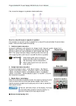
Remote Sensing is applied to keep regulation from degrading which might occur due to the
voltage drop between the output connection of the power supply and the load.
After connecting the power supply to the load, voltage is sensed at the load rather than at the
power supply’s output terminals. This connection allows the power supply to generate
sufficient voltage to the load automatically due to the voltage drop in applications with long
lead lengths, and read back an accurate voltage directly over the load.
When the Remote Voltage Sense is applied, the OVP circuit senses the voltage at the load
terminals, not the power supply output terminals.
Note
62015L-60-6 opens this function after S/N: L02000000122.
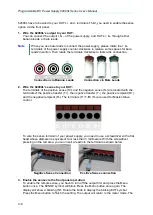
How to use Remote Voltage Sense
There are three steps to use the Remote Voltage Sense. First of all, the and – of the
62000L have to be wired to your DUT’s + and - terminals. Second, the sense + and – of the


