


13- 11- 605
Page 39
SECTION 5
LUBRICATION
COMPRESSOR OIL SYSTEM
-- The air end oil reser-
voir is filled with oil and the inlet bearing lubrication fit-
tings are greased at the factory before shipment. A tag
on the reservoir fill cap indicates the type of oil in the
reservoir as it left the factory.
RECOMMENDED LUBRICANT
-- Champion com-
pressors are factory filled with RotorLub
t
lubricants.
These lubricants are formulated to the highest quality
standards and are factory authorized, tested and ap-
proved for use in rotary screw compressors.
RotorLub
t
lubricants are available through your au-
thorized Champion compressor distributor.
OIL SPECIFICATIONS
-- The air end reservoir is
factory filled with RotorLub
t
800 lubricant. A lubricant
analysis program for a periodic check of lubricant quali-
ty and remaining life can maximize the change interval.
For grease specifications, refer to “Electric Motor
Grease Specifications,” page 14.
Material Safety Data Sheets (MSDS) are available for
all RotorLub lubricants from your authorized Champion
distributor or by calling 815-- 875-- 3321.
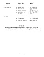
Use of improper lubricants will cause
damage to equipment. Do not mix dif-
ferent types of lubricants or use infe-
rior lubricants.
Improper equipment maintenance
with use of synthetic lubricants will
damage equipment. Oil change inter-
vals must be adhered to for maximum
compressor protection and efficiency
See Maintenance Schedule, page 45.
High temperature operation can
cause damage to equipment or per-
sonal injury.
Do not repeatedly restart the unit after
high temperature stops operation.
Find and correct the malfunction be-
fore resuming operation.
LUBRICANT MAINTENANCE INTERVAL
-- The oil
reservoir at the discharge end of the air end has a ca-
pacity of approximately 32 oz. (.8 L). The oil bath type
lubrication utilized does not require an oil filter or dedi-
cated circulation hardware. As such, discharge end lu-
bricant change intervals of 2000 hours are recom-
mended as the only maintenance requirement in lieu of
filter changes and circulation system maintenance.
The drive end bearings of the air end should be lubri-
cated with the prescribed grease every 1000 hours of
operation until a small amount comes lightly out of the
relief holes on the lower sides of the compressor inlet
end or on the inlet end cover.
During initial start-- up and after regreasing, a small
amount of grease may be ejected from the relief holes.
Wipe off any excess lubricant.
Severe operating conditions may require shorter re-
greasing intervals.
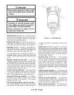
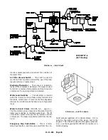
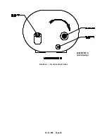
OIL LEVEL SIGHT GLASS
(FIGURE 1-- 3, page 2,
and FIGURE 5-- 1, page 40) indicates the amount of oil
in the air end oil reservoir. Read the oil level when the
unit is off. In operation the oil level may fluctuate.
Add oil only when the oil level drops into the lower half
of the glass. Drain oil only when the compressor is off.
Содержание ROTORCHAMP RCOF20
Страница 13: ...13 11 605 Page 4 FIGURE 1 6 AIR WATER SCHEMATIC 300EWC797 B Ref Drawing ...
Страница 16: ...13 11 605 Page 7 DECALS 206EAQ077 300EWC077 301EWC077 211EAQ077 207EAQ077 ...
Страница 17: ...13 11 605 Page 8 DECALS 216EAQ077 206EWD077 222EAQ077 221EAQ077 208EAQ077 ...
Страница 31: ...13 11 605 Page 22 FIGURE 4 2 FLOW CHART FOR SET UP PROGRAMMING 300EWC1255 Ref Drawing ...
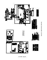
Страница 41: ...13 11 605 Page 32 FIGURE 4 6 CONTROL TUBING SCHEMATIC 300EWC797 B Ref Drawing ...
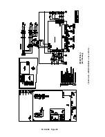
Страница 43: ...13 11 605 Page 34 FIGURE 4 8 CONTROL SCHEMATIC COMPRESSOR UNLOADED CONSTANT SPEED MODE 303EWC797 A Ref Drawing ...
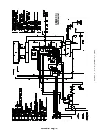
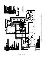
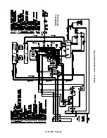
Страница 45: ...13 11 605 Page 36 FIGURE 4 10 WIRING DIAGRAM FULL VOLTAGE 301EWC546 A Ref Drawing ...
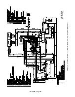
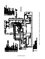
Страница 46: ...13 11 605 Page 37 FIGURE 4 11 WIRING DIAGRAM WYE DELTA 302EWC546 A Ref Drawing ...
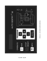
Страница 47: ...13 11 605 Page 38 FIGURE 4 12 AUTO SENTRY W CONTROLLER DISPLAY ...
Страница 49: ...13 11 605 Page 40 FIGURE 5 1 OIL LEVEL SIGHT GLASS 306EWC797 A Ref Drawing ...
Страница 50: ...13 11 605 Page 41 FIGURE 5 2 FLOW DIAGRAM AIR COOLED 300EWC797 A Ref Drawing ...


