


13- 11- 603
Page 11
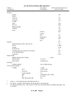
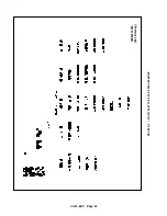
Maximum Limit
1)
Total Hardness as CaCO
3
120 parts per million
2)
Either Total Dissolved Solids
500 parts per million
or Specific Conductance
800 Micromhos/cm
3)
pH
7.5 to 9.0
FIGURE 2--3 -- ADDITIONAL WATER LIMITATIONS
Total Hardness
in Mg/L* as CaCO
3
Water Classification
0 -- 60
Soft
61 -- 120
Moderately Hard
120 -- 180
Hard
Greater than 180
Very Hard
FIGURE 2--4 -- USGS CLASSIFICATION OF WATER
* 1 Mg/L = Approx. 1 ppm
In addition to the requirements of the National Drinking
Water Regulations, the limits listed in FIGURE 2-- 3
shall not be exceeded.
Use of compressor initial fill and
make--up water exceeding these lim-
its could result in excessive scale
formation which can facilitate corro-
sive activity and equipment damage
or malfuction.
This unit is equipped with a food-- grade hexameta-
phosphate feeder cartridge which dissolves slowly in
water to prevent scale and inhibit corrosive activity.
The use of a water considered to be “hard” or “very
hard” by the U.S. Geological Survey (See FIGURE 2-- 4
for the U.S.G.S. classification of water) will result in in-
creased frequency of required water filter and cartridge
replacements and lead to scale build-- up which can
cause equipment malfunction and/or damage. If a pro-
posed water supply is questionable, the water should
be analyzed. If the water does not comply with this
specification, a water treatment service can recom-
mend equipment to satisfy this specification. Hardness
can often be reduced by using a sodium ion exchange
water softener. The use of deionized water is not rec-
ommended.
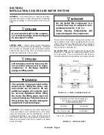
AUXILIARY AIR RECEIVER
-- An auxiliary air receiv-
er is not required if the piping system is large and pro-
vides sufficient storage capacity to prevent rapid cycl-
ing. When used, an air receiver should be of adequate
size, provided with a relief valve of proper setting, a
pressure gauge and a means of draining condensate.
MOISTURE SEPARATOR/TRAP
-- Since the unit is
equipped with a built-- in aftercooler, an integral mois-
ture separator and drain trap is furnished with the unit.
The moisture from the trap is piped to the unit drain line.
CONTROL PIPING
-- External control piping is not nec-
essary since the unit is factory wired and piped for the
control system specified.
INLET LINE
-- Where an inlet line is used between the
air filter and the compressor, it must be thoroughly
cleaned on the inside to prevent dirt or scale from en-
tering the compressor.
If welded construction is
used, the line must be shot blasted and cleaned to
remove welding scale.
In either case, the inlet line
must be coated internally by galvanizing or painting
with a moisture and oil-- proof sealing lacquer. Up to ten
(10) feet in length, the inlet line should be the full size
of the inlet opening on the compressor. If an extra--
long line is necessary, the pipe size should be in-
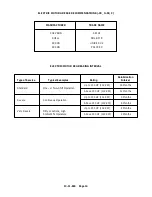
creased according to Inlet Line Chart, FIGURE 2-- 5.
Accessibility for inlet air filter servicing must be consid-
ered when relocating the filters from the unit to a remote
location.
Length of Inlet Line
Diameter of Pipe Size
0 to 10 Feet (0 to 3 Meters)
Same as Compressor Inlet Opening
. . . . . . . . . . . . . . . . . . . . . . . . . . . . . . . . . .
10 to 17 Feet (3 to 5 Meters)
One Size Larger Than Inlet Opening
. . . . . . . . . . . . . . . . . . . . . . . . . . . . . . . . . .
17 to 38 Feet (5 to 11.5 Meters)
Two Sizes Larger Than Inlet Opening
. . . . . . . . . . . . . . . . . . . . . . . . . . . . . . .
FIGURE 2--5 -- INLET LINE LENGTHS
Содержание ROTORCHAMP RCOF20
Страница 13: ...13 11 605 Page 4 FIGURE 1 6 AIR WATER SCHEMATIC 300EWC797 B Ref Drawing ...
Страница 16: ...13 11 605 Page 7 DECALS 206EAQ077 300EWC077 301EWC077 211EAQ077 207EAQ077 ...
Страница 17: ...13 11 605 Page 8 DECALS 216EAQ077 206EWD077 222EAQ077 221EAQ077 208EAQ077 ...
Страница 31: ...13 11 605 Page 22 FIGURE 4 2 FLOW CHART FOR SET UP PROGRAMMING 300EWC1255 Ref Drawing ...
Страница 41: ...13 11 605 Page 32 FIGURE 4 6 CONTROL TUBING SCHEMATIC 300EWC797 B Ref Drawing ...
Страница 43: ...13 11 605 Page 34 FIGURE 4 8 CONTROL SCHEMATIC COMPRESSOR UNLOADED CONSTANT SPEED MODE 303EWC797 A Ref Drawing ...
Страница 45: ...13 11 605 Page 36 FIGURE 4 10 WIRING DIAGRAM FULL VOLTAGE 301EWC546 A Ref Drawing ...
Страница 46: ...13 11 605 Page 37 FIGURE 4 11 WIRING DIAGRAM WYE DELTA 302EWC546 A Ref Drawing ...
Страница 47: ...13 11 605 Page 38 FIGURE 4 12 AUTO SENTRY W CONTROLLER DISPLAY ...
Страница 49: ...13 11 605 Page 40 FIGURE 5 1 OIL LEVEL SIGHT GLASS 306EWC797 A Ref Drawing ...
Страница 50: ...13 11 605 Page 41 FIGURE 5 2 FLOW DIAGRAM AIR COOLED 300EWC797 A Ref Drawing ...


