


13- 11- 605
Page 6
Failure to observe these notices could result in damage to equipment.
D
Stop the unit if any repairs or adjustments on or around the compressor are
required.
D
Disconnect the compressor unit from its power source, tag and lockout be-
fore working on the unit -- this machine is automatically controlled and may
start at any time.
D
An Excess Flow Valve should be on all compressed air supply hoses ex-
ceeding 1/2 inch inside diameter. (OSHA Regulation, Section 1926.302)
D
Do not exceed the rated maximum pressure values shown on the nameplate.
D
Do not operate unit if safety devices are not operating properly. Check peri-
odically. Never bypass safety devices.
Содержание ROTORCHAMP RCOF20
Страница 13: ...13 11 605 Page 4 FIGURE 1 6 AIR WATER SCHEMATIC 300EWC797 B Ref Drawing ...
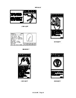
Страница 16: ...13 11 605 Page 7 DECALS 206EAQ077 300EWC077 301EWC077 211EAQ077 207EAQ077 ...
Страница 17: ...13 11 605 Page 8 DECALS 216EAQ077 206EWD077 222EAQ077 221EAQ077 208EAQ077 ...
Страница 31: ...13 11 605 Page 22 FIGURE 4 2 FLOW CHART FOR SET UP PROGRAMMING 300EWC1255 Ref Drawing ...
Страница 41: ...13 11 605 Page 32 FIGURE 4 6 CONTROL TUBING SCHEMATIC 300EWC797 B Ref Drawing ...
Страница 43: ...13 11 605 Page 34 FIGURE 4 8 CONTROL SCHEMATIC COMPRESSOR UNLOADED CONSTANT SPEED MODE 303EWC797 A Ref Drawing ...
Страница 45: ...13 11 605 Page 36 FIGURE 4 10 WIRING DIAGRAM FULL VOLTAGE 301EWC546 A Ref Drawing ...
Страница 46: ...13 11 605 Page 37 FIGURE 4 11 WIRING DIAGRAM WYE DELTA 302EWC546 A Ref Drawing ...
Страница 47: ...13 11 605 Page 38 FIGURE 4 12 AUTO SENTRY W CONTROLLER DISPLAY ...
Страница 49: ...13 11 605 Page 40 FIGURE 5 1 OIL LEVEL SIGHT GLASS 306EWC797 A Ref Drawing ...
Страница 50: ...13 11 605 Page 41 FIGURE 5 2 FLOW DIAGRAM AIR COOLED 300EWC797 A Ref Drawing ...


