


13- 11- 605
Page 1
SECTION 1
GENERAL INFORMATION
FIGURE 1--1 -- TYPICAL COMPRESSION CYCLE
COMPRESSOR
-- The Champion Rotary Screw com-
pressor is a single stage, positive displacement rotary
machine using meshing helical rotors to effect com-
pression. Both rotors are supported between high ca-
pacity roller bearings located outside the compression
chamber. Single width cylindrical roller bearings are
used at the inlet end of the rotors to carry part of the ra-
dial loads. Angular contact ball bearings at the dis-
charge end locate each rotor axially and carry all thrust
loads and the remainder of the radial loads.
COMPRESSION PRINCIPLE
(FIGURE 1-- 1) -- Com-
pression is accomplished by the main and secondary
rotors synchronously meshing in a one-- piece cylinder.
The main rotor has six (6) helical lobes 60
_
apart. The
secondary rotor has eight (8) matching helical grooves
45
_
apart to allow meshing with main rotor lobes.
The air inlet port is located on top of the compressor cyl-
inder near the drive shaft end. The discharge port is at
the bottom on the opposite end of the compressor cylin-
der. FIGURE 1-- 1 is an inverted view to show inlet and
discharge ports. The compression cycle begins as ro-
tors unmesh at the inlet port and air is drawn into the
cavity between the main rotor lobes and secondary ro-
tor grooves (A). When the rotors pass the inlet port cut-
off, air is trapped in the interlobe cavity and flows axially
with the meshing rotors (B). As meshing continues,
more of the main rotor lobe enters the secondary rotor
grove, normal volume is reduced and pressure in-
creases.
Water is injected into the cylinder to remove the heat of
compression and seal internal clearances. Volume re-
duction and pressure increase continues until the air/
water mixture trapped in the interlobe cavity by the ro-
tors passes the discharge port and is released to the
air/water reservoir (C). Each rotor cavity follows the
same “fill-- compress-- discharge” cycle in rapid succes-
sion to produce a discharge air flow that is continuous,
smooth, and shock free.
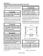
AIR FLOW IN THE COMPRESSOR SYSTEM
(FIGURE 1-- 4, page 3) -- Air enters the air filter and
passes through the inlet unloader valve to the com-
pressor. After compression, the air/water mixture flows
to the separator/reservoir tank where most of the water
is removed by velocity change and impingement. The
air flows to the aftercooler, then to the moisture separa-
tor where the water that has condensed out is removed
from the air stream. The air then flows through the
package discharge check valve and to the plant air sys-
tem.
WATER SYSTEM
(FIGURE 1-- 6, page 4) -- Water is
forced by air pressure from the separator/reservoir
tank through the heat exchanger, the system water fil-
ter and into the water injection manifold where the wa-
ter is distributed to the compression chamber injection
ports. The water removes the heat of compression and
seals internal clearances. Seals minimize water leak-
age out of the compression chamber.
LUBRICATION
-- Oil in the oil reservoir at the dis-
charge end of the air end lubricates the discharge end
bearings. Grease fittings are located at the inlet end of
the air end for periodic lubrication of the inlet end bear-
ings.
Содержание ROTORCHAMP RCOF20
Страница 13: ...13 11 605 Page 4 FIGURE 1 6 AIR WATER SCHEMATIC 300EWC797 B Ref Drawing ...
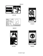
Страница 16: ...13 11 605 Page 7 DECALS 206EAQ077 300EWC077 301EWC077 211EAQ077 207EAQ077 ...
Страница 17: ...13 11 605 Page 8 DECALS 216EAQ077 206EWD077 222EAQ077 221EAQ077 208EAQ077 ...
Страница 31: ...13 11 605 Page 22 FIGURE 4 2 FLOW CHART FOR SET UP PROGRAMMING 300EWC1255 Ref Drawing ...
Страница 41: ...13 11 605 Page 32 FIGURE 4 6 CONTROL TUBING SCHEMATIC 300EWC797 B Ref Drawing ...
Страница 43: ...13 11 605 Page 34 FIGURE 4 8 CONTROL SCHEMATIC COMPRESSOR UNLOADED CONSTANT SPEED MODE 303EWC797 A Ref Drawing ...
Страница 45: ...13 11 605 Page 36 FIGURE 4 10 WIRING DIAGRAM FULL VOLTAGE 301EWC546 A Ref Drawing ...
Страница 46: ...13 11 605 Page 37 FIGURE 4 11 WIRING DIAGRAM WYE DELTA 302EWC546 A Ref Drawing ...
Страница 47: ...13 11 605 Page 38 FIGURE 4 12 AUTO SENTRY W CONTROLLER DISPLAY ...
Страница 49: ...13 11 605 Page 40 FIGURE 5 1 OIL LEVEL SIGHT GLASS 306EWC797 A Ref Drawing ...
Страница 50: ...13 11 605 Page 41 FIGURE 5 2 FLOW DIAGRAM AIR COOLED 300EWC797 A Ref Drawing ...


