


13- 11- 605
Page 18
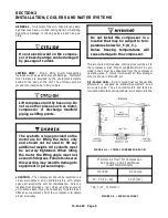
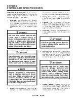
SECTION 4
CONTROLS & INSTRUMENTATION
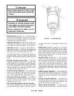
GENERAL DESCRIPTION
-- The Champion Rotor-
Champ
R
waterflooded rotary screw compressor is pre-
wired with all controls, motor, and starter for the voltage
and horsepower at the time of ordering. It is necessary
only to connect the compressor unit to the correct pow-
er supply, to the shop air line, and to the appropriate wa-
ter supply. A standard compressor unit consists of the
compressor, water reservoir, water cooling system and
filters, lubrication reservoir, motor type as specified,
NEMA 12 starter / control box, and control components
as described below.
This
compressor
unit
features
the
AUTO
SENTRY
R
-- W controller, which integrates all the con-
trol functions under microprocessor control. Its func-
tions include safety and shutdown, compressor regula-
tion, operator control, and advisory / maintenance
indicators. The keypad and display provide the opera-
tor with a logical and easily operated control of the com-
pressor and indication of its condition.
AUTO SENTRY
R
- W OPERATION
Normal operation is controlled by the keys in the OP-
ERATE island of the AUTO SENTRY
R
-- W controller.
Prior to starting, press the [STOP/RESET] key to place
the controller into its READY state (as indicated on the
display). Press the [RUN] key to start the compressor.
The green LED will light near the automatic operation
symbol whenever operation is enabled.
The [STOP/RESET] key may be pressed at any time
to stop the compressor under normal conditions. If the
compressor has been running, the reservoir pressure
is relieved before stopping the motor. The display will
count down to zero during the normal stop.
An optional control may be wired into the AUTO
SENTRY
R
-- W controller to interrupt and restart the unit
based on controls by others. When stopped by these
controls, the display indicates remote stop.
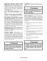
Automatic restarting or electrical
shock can cause injury or death.
Open, tag and lockout main discon-
nect and any other circuits before
servicing the unit.
In any mode, the compressor will start only if reservoir
pressure is below 5 psig (0.3 bars). The display will in-
dicate if the control is waiting for a reservoir blowdown,
along with the remaining pressure. The controls also
delay initial loading of the compressor until a startup
delay has been completed.
Constant Run Mode Operation
-- This mode is best
used in applications where there are no long periods of
unloaded operation, or for minimum response time to
sudden demands. The compressor unit will start and
run continuously, using its controls to load and unload
the compressor. This matches average delivery to de-
mand.
When the air demand is less than the compressor ca-
pacity, the air pressure rises to the unload point of the
control. It will then unload (but not blow down) and will
not deliver any air to the system. Air demands are sup-
plied by air stored in receivers and plant piping. When
the pressure falls to halfway between the unload and
load pressures, the W controller again fully loads the
compressor.
When first starting, the controller will keep the com-
pressor fully unloaded and blown down until the system
pressure drops below the load pressure. Once loaded,
the reservoir will remain fully charged, regardless of de-
mand. Responses to demand are thus immediate, and
system pressures will be maintained in the upper por-
tion of the programmed pressure band.
Low Demand Mode Operation
-- The low demand
mode reduces power consumption by relieving pres-
sure in the reservoir during unloaded operation. This
mode is best used where there is moderate air storage
and there are unloaded periods during the day, but fre-
quent motor starting and stopping is undesirable. Dur-
ing periods of moderate to high demands, this mode is
identical to the constant-- run mode described above.
During low demand periods, the controller will also
open the blowdown valve while unloaded, to minimize
the motor load. A timer is reset when this occurs. Plant
demands and control air pressure is supplied from the
plant air system while the compressor is unloaded.
When the system air pressure drops to the load pres-
sure, the blowdown valve recloses and the compressor
fully loads.
Subsequent blowdown periods are not allowed until the
timer has completed its cycle. This cycle eliminates
frequent blowdowns while the plant has high air de-
mands, and the energy required to re-- pressurize the
reservoir. The timer is adjustable from 1 to 20 minutes.
Automatic Mode Operation
-- This mode provides
automatic start and timed stop, and is best used in ap-
plications with long unloaded periods and adequate
Содержание ROTORCHAMP RCOF20
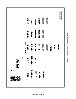
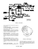
Страница 13: ...13 11 605 Page 4 FIGURE 1 6 AIR WATER SCHEMATIC 300EWC797 B Ref Drawing ...
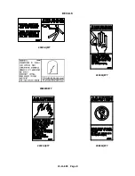
Страница 16: ...13 11 605 Page 7 DECALS 206EAQ077 300EWC077 301EWC077 211EAQ077 207EAQ077 ...
Страница 17: ...13 11 605 Page 8 DECALS 216EAQ077 206EWD077 222EAQ077 221EAQ077 208EAQ077 ...
Страница 31: ...13 11 605 Page 22 FIGURE 4 2 FLOW CHART FOR SET UP PROGRAMMING 300EWC1255 Ref Drawing ...
Страница 41: ...13 11 605 Page 32 FIGURE 4 6 CONTROL TUBING SCHEMATIC 300EWC797 B Ref Drawing ...
Страница 43: ...13 11 605 Page 34 FIGURE 4 8 CONTROL SCHEMATIC COMPRESSOR UNLOADED CONSTANT SPEED MODE 303EWC797 A Ref Drawing ...
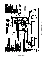
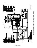
Страница 45: ...13 11 605 Page 36 FIGURE 4 10 WIRING DIAGRAM FULL VOLTAGE 301EWC546 A Ref Drawing ...
Страница 46: ...13 11 605 Page 37 FIGURE 4 11 WIRING DIAGRAM WYE DELTA 302EWC546 A Ref Drawing ...
Страница 47: ...13 11 605 Page 38 FIGURE 4 12 AUTO SENTRY W CONTROLLER DISPLAY ...
Страница 49: ...13 11 605 Page 40 FIGURE 5 1 OIL LEVEL SIGHT GLASS 306EWC797 A Ref Drawing ...
Страница 50: ...13 11 605 Page 41 FIGURE 5 2 FLOW DIAGRAM AIR COOLED 300EWC797 A Ref Drawing ...


