


13- 11- 605
Page 29
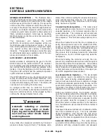
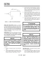
Never paint, lubricate or alter a relief
valve. Do not plug vent or restrict dis-
charge.
Operation of unit with improper relief
valve setting can result in severe per-
sonal injury or machine damage.
Insure properly set valves are in-
stalled and maintained.
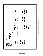
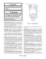
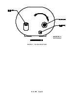
Blowdown Valve
(FIGURE 4-- 3) -- This valve normal-
ly is used for control functions, but also serves to relieve
reservoir pressure following a shutdown. See addition-
al blowdown valve description below.
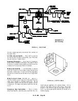
Discharge Check Valve -
(FIGURE 1-- 4, page 3) -- A
check valve to prevent back flow of air from the shop
air line when the unit stops, unloads, or is shut down.
Inlet Valve
(FIGURE 1-- 3, page 2, and FIGURE 4-- 4,
page 30, this section) -- The Inlet valve opens to load
and closes to unload the compressor. At shutdown, the
inlet valve closes to prevent the back flow of air.
The inlet valve position is controlled by air pressure in
its piston cylinder, which is controlled by the AUTO
SENTRY
R
-- W through the magnetic unloader solenoid
valve.
Magnetic Unloader Solenoid Valve
-- This valve
controls the position of the inlet valve in response to the
AUTO SENTRY
R
-- W. With the valve de-- energized,
the normally open unloader valve allows control pres-
sure to the inlet piston to close the inlet valve. If the
valve is energized, control pressure is relieved from the
inlet piston to allow the valve to open.
Control Air Pressure Regulator
-- This pressure reg-
ulator is used to supply a constant and low control pres-
sure to prevent damage to the inlet valve from “slam-
ming.” The regulator should be set for 25-- 30 psig.
Seal Purge Air Pressure Regulator
-- This pressure
regulator is used to provide a constant and low control
pressure for proper seal operation.
The regulator
should be set for 5-- 7 psig.
Inlet Seal Buffering Water Pressure Regulator
--
This pressure regulator is used to provide a constant
and low pressure water supply for proper operation of
FIGURE 4--3 -- BLOWDOWN VALVE
compressor inlet seals. The regulator should be set for
2-- 3 psig.
Shuttle Valve
(FIGURE 4-- 5, page 30) -- Also known
as a double check valve, the shuttle valve is a device
which will take two (2) supply signals and allow the one
with the highest pressure to pass through. The shuttle
valve is used to provide control air pressure from either
the reservoir or plant air system, as required during dif-
ferent operating conditions.
Blowdown Valve
(FIGURE 4-- 3)
-- The blowdown
valve is a two-- way solenoid valve which is piped into
the water reservoir outlet ahead of the discharge check
valve. When the solenoid is de-- energized, the valve
opens and the coolant system is blown down. When
the solenoid is energized, the valve closes to allow the
coolant system to pressurize. A control air check valve
is provided to ensure that the inlet valve is closed during
blowdown.
System Pressure Transducer
-- This transducer is
connected after the discharge check valve. It converts
the pressure in the plant air system into an electrical
signal for use by the AUTO SENTRY
R
-- W controller for
control.
Reservoir Pressure Transducer
-- This transducer
is connected to the coolant system. Its signal is used
to prevent loaded starts, monitor coolant pressure, and
monitor the condition of the water filter.
Injection Pressure Transducer
-- This transducer is
connected to the coolant system. Its signal is used to
Содержание ROTORCHAMP RCOF20
Страница 13: ...13 11 605 Page 4 FIGURE 1 6 AIR WATER SCHEMATIC 300EWC797 B Ref Drawing ...
Страница 16: ...13 11 605 Page 7 DECALS 206EAQ077 300EWC077 301EWC077 211EAQ077 207EAQ077 ...
Страница 17: ...13 11 605 Page 8 DECALS 216EAQ077 206EWD077 222EAQ077 221EAQ077 208EAQ077 ...
Страница 31: ...13 11 605 Page 22 FIGURE 4 2 FLOW CHART FOR SET UP PROGRAMMING 300EWC1255 Ref Drawing ...
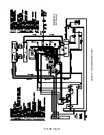
Страница 41: ...13 11 605 Page 32 FIGURE 4 6 CONTROL TUBING SCHEMATIC 300EWC797 B Ref Drawing ...
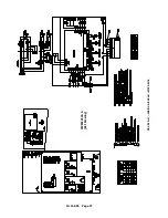
Страница 43: ...13 11 605 Page 34 FIGURE 4 8 CONTROL SCHEMATIC COMPRESSOR UNLOADED CONSTANT SPEED MODE 303EWC797 A Ref Drawing ...
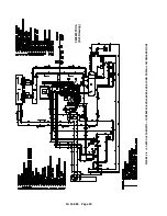
Страница 45: ...13 11 605 Page 36 FIGURE 4 10 WIRING DIAGRAM FULL VOLTAGE 301EWC546 A Ref Drawing ...
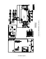
Страница 46: ...13 11 605 Page 37 FIGURE 4 11 WIRING DIAGRAM WYE DELTA 302EWC546 A Ref Drawing ...
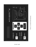
Страница 47: ...13 11 605 Page 38 FIGURE 4 12 AUTO SENTRY W CONTROLLER DISPLAY ...
Страница 49: ...13 11 605 Page 40 FIGURE 5 1 OIL LEVEL SIGHT GLASS 306EWC797 A Ref Drawing ...
Страница 50: ...13 11 605 Page 41 FIGURE 5 2 FLOW DIAGRAM AIR COOLED 300EWC797 A Ref Drawing ...


