


13- 11- 605
Page 50
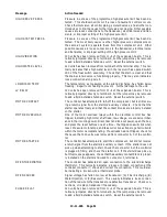
HIGH DISCH TEMP
The temperature was greater than 180 degrees F (82 degrees C) at the
airend discharge. Ensure that the compressor receives adequate cooling
air or water, and that the coolers are not plugged.
LOW AMB TEMP
The temperature was less than 40 degrees F (4 degrees C) at the airend
discharge. Ensure that the compressor is located in a room kept above
freezing.
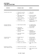
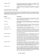
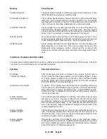
SHUTDOWN TROUBLE SHOOTING GUIDE
All shutdowns are indicated on the keypad by the word “SHUTDOWN” on the top line of the display, and one of the
following messages on the lower line of the display. The red indicator in the Status area will be steadily lit while the
conditions exist, and will flash after the condition has been corrected. Perform service as indicated. Press the
[STOP/RESET] key to clear the shutdown.
Message
Action Needed
BAD FLOAT SWITCH
120 volts is present at both terminal 6 and 7 of the terminal strip. This indi-
cates a likely wiring error to the float switch; check and correct. It may also
indicate a short within the switch itself.
CHECK CN7
All inputs at connector 7 of the controller are off. The most common cause
for this is that the connector plug has been pulled out. Plug the connector
back in firmly.
CHECK CN5
120 volts has been removed from ALL inputs to connector 5 of the control-
ler. The most common cause for this is that the connector plug has been
pulled out. Plug the connector back in firmly.
CHNG H2O FILTER
The differential pressure across the water filter has risen to over 40 psid.
Change the filter to ensure an adequate flow of coolant.
EMERGENCY STOP
The Emergency Stop button has been pressed. Pull it back out to its nor-
mal position. If the button has not been pressed, check that the contact
block is firmly mounted in the right or left (not center) position of the opera-
tor. Check for loose connections which would remove 120 volts from con-
nector 5-- 8 of the controller.
EXTERNAL DEVICE
120 volts has been removed from J1-- 4 of the expansion board. This is
normally jumpered directly to terminal 9, but the jumper may be removed
to add a field installed shutdown switch. Reset the external switch.
HIGH DIS TEMP R
This indicates that the controller has detected a rapid temperature rise in
the airend discharge. This normally would indicate a loss of coolant injec-
tion into the airend. Completely check all water piping, the filter, and flow
controls for blockage or freezing. This may also be caused by a loose con-
nection at connector 7 of the controller. Monitor the temperature carefully
during restarts after servicing.
HIGH DISCH TEMP
This indicates that the controller has detected temperature in excess of
the programmed high temperature limit at the airend discharge. The most
common cause for this is inadequate package cooling. Ensure proper air
flow for air-- cooled units, or adequate cooling water for water cooled units.
Monitor the temperature carefully during restarts after servicing.
HIGH INJ PRESS
Pressure in excess of the programmed high pressure limit has been de-
tected. This shutdown will occur if a loss of pneumatic controls occurs.
Check the inlet valve, all control piping, solenoid valves, and all other con-
trol devices to find the cause for the inlet valve not closing. Other possible
causes are loose connections to the transducer, electrical noise and tran-
sients, or improper setting of the high pressure limit.
Содержание ROTORCHAMP RCOF20
Страница 13: ...13 11 605 Page 4 FIGURE 1 6 AIR WATER SCHEMATIC 300EWC797 B Ref Drawing ...
Страница 16: ...13 11 605 Page 7 DECALS 206EAQ077 300EWC077 301EWC077 211EAQ077 207EAQ077 ...
Страница 17: ...13 11 605 Page 8 DECALS 216EAQ077 206EWD077 222EAQ077 221EAQ077 208EAQ077 ...
Страница 31: ...13 11 605 Page 22 FIGURE 4 2 FLOW CHART FOR SET UP PROGRAMMING 300EWC1255 Ref Drawing ...
Страница 41: ...13 11 605 Page 32 FIGURE 4 6 CONTROL TUBING SCHEMATIC 300EWC797 B Ref Drawing ...
Страница 43: ...13 11 605 Page 34 FIGURE 4 8 CONTROL SCHEMATIC COMPRESSOR UNLOADED CONSTANT SPEED MODE 303EWC797 A Ref Drawing ...
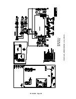
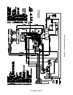
Страница 45: ...13 11 605 Page 36 FIGURE 4 10 WIRING DIAGRAM FULL VOLTAGE 301EWC546 A Ref Drawing ...
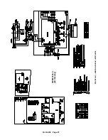
Страница 46: ...13 11 605 Page 37 FIGURE 4 11 WIRING DIAGRAM WYE DELTA 302EWC546 A Ref Drawing ...
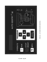
Страница 47: ...13 11 605 Page 38 FIGURE 4 12 AUTO SENTRY W CONTROLLER DISPLAY ...
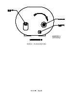
Страница 49: ...13 11 605 Page 40 FIGURE 5 1 OIL LEVEL SIGHT GLASS 306EWC797 A Ref Drawing ...
Страница 50: ...13 11 605 Page 41 FIGURE 5 2 FLOW DIAGRAM AIR COOLED 300EWC797 A Ref Drawing ...