


13- 11- 605
Page 19
storage to allow the compressor to be stopped for peri-
ods of light demands. Operation during periods of
moderate to heavy demands is identical to the low de-
mand and constant run modes described above.
The automatic time delay is adjustable from 5 to 20
minutes. If the controller operates unloaded for this pe-
riod with no demand, the compressor drive motor is
halted to eliminate its power consumption. The con-
trols will remain in this state until pressure drops below
the load pressure.
This is the most common selected mode of operation,
as it automatically will operate the compressor unit in
the most efficient manner for the demand of the air sys-
tem.
Sequence Mode Operation
-- This mode provides for
communication between controllers, operating only as
many as are required for economical operation. This
is best used on applications with large storage capacity
and diverse loads. The lead unit will operate identically
to the automatic mode; operation will be automatically
staged for each lag unit (up to 8 total). For more in-
formation, refer to the sequencing instructions later in
this chapter.
An optional expansion board must be installed for se-
quencing operation. Communication between control-
lers is achieved by interconnection of a communica-
tions cable to expansion board connectors. A ”unit
number” must be assigned to each unit in this mode,
but the display will indicate the unit’s actual operating
ranking.
AUTO- SENTRY
R
- W CONTROL DISPLAY
The display above the keypad is used to provide oper-
ating information to the user. If a shutdown has oc-
curred, the display will indicate the cause.
During normal operation, the display will show the sys-
tem pressure, compressor discharge temperature, to-
tal running hours, and operation mode. Alternate dis-
plays are available by pressing the [?] INFO or the
keypad cursor [<] [>] keys, and will be identified on the
display. These include:
Water Filter Differential Pressure
DIF PRES
Reservoir Pressure
RES PRES
Water Injection Pressure
INJ PRES
System Pressure
SYS PRES
Compressor Discharge Temperature
DIS TMP
Total Hours
TOT HRS
Loaded Hours
LOAD HRS
FIGURE 4--1 -- AUTO SENTRY
R
--W CONTROLLER DISPLAY
Содержание ROTORCHAMP RCOF20
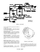
Страница 13: ...13 11 605 Page 4 FIGURE 1 6 AIR WATER SCHEMATIC 300EWC797 B Ref Drawing ...
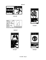
Страница 16: ...13 11 605 Page 7 DECALS 206EAQ077 300EWC077 301EWC077 211EAQ077 207EAQ077 ...
Страница 17: ...13 11 605 Page 8 DECALS 216EAQ077 206EWD077 222EAQ077 221EAQ077 208EAQ077 ...
Страница 31: ...13 11 605 Page 22 FIGURE 4 2 FLOW CHART FOR SET UP PROGRAMMING 300EWC1255 Ref Drawing ...
Страница 41: ...13 11 605 Page 32 FIGURE 4 6 CONTROL TUBING SCHEMATIC 300EWC797 B Ref Drawing ...
Страница 43: ...13 11 605 Page 34 FIGURE 4 8 CONTROL SCHEMATIC COMPRESSOR UNLOADED CONSTANT SPEED MODE 303EWC797 A Ref Drawing ...
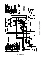
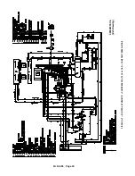
Страница 45: ...13 11 605 Page 36 FIGURE 4 10 WIRING DIAGRAM FULL VOLTAGE 301EWC546 A Ref Drawing ...
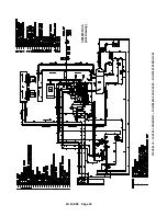
Страница 46: ...13 11 605 Page 37 FIGURE 4 11 WIRING DIAGRAM WYE DELTA 302EWC546 A Ref Drawing ...
Страница 47: ...13 11 605 Page 38 FIGURE 4 12 AUTO SENTRY W CONTROLLER DISPLAY ...
Страница 49: ...13 11 605 Page 40 FIGURE 5 1 OIL LEVEL SIGHT GLASS 306EWC797 A Ref Drawing ...
Страница 50: ...13 11 605 Page 41 FIGURE 5 2 FLOW DIAGRAM AIR COOLED 300EWC797 A Ref Drawing ...


