


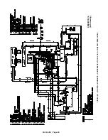

13- 11- 605
Page 20
Remaining Blowdown Time
BD TMR
Remaining Auto Time
AUTO TMR
Remaining blowdown and auto times are only available
in Low Demand, Automatic, and Sequence modes, as
appropriate.
If no keys are pressed for 5 seconds, the display will re-
vert to its normal mode.
The display is also used as a service reminder for nor-
mal maintenance items. If service is recommended,
the yellow LED next to the service symbol will come on,
and a message will alternate with the normal lower line
message. These messages are intended to advise of
conditions which may lead to a shutdown.
If a protective shutdown occurs, the red LED next to the
shutdown symbol will be on and the top line of the dis-
play will indicate “SHUTDOWN.” The lower line will in-
dicate the cause of the shutdown.
SERVICE ADVISORIES
The AUTO SENTRY
R
-- W controller turns on an advi-
sory when it detects operation which needs service
attention, but does not warrant shutting down the com-
pressor. Some of these are normal maintenance pro-
cedures, and are intended to serve as a reminder to
perform routine service. Others are conditions which
can reduce the maximum compressor performance. It
will remain in effect until reset. Check the display dur-
ing routine inspections, and perform maintenance as
suggested. Refer to the troubleshooting section for de-
tailed information about each advisory.
Temperature advisories may be cleared while the unit
is running by simply pressing the [ENTER] key. To re-
set the service advisories, press the [STOP/RESET]
key to stop operation of the compressor. After it has
stopped, disconnect power and service as required.
After servicing, restore power and reset the controller
as indicated in the programming / maintenance section
below.
PROTECTIVE SHUTDOWNS
The AUTO SENTRY
R
-- W will shut down the unit fol-
lowing any fault detected in the following devices.
Long-- term problems will have a brief blowdown period
before fully shutting down. Following a shutdown, a
message will be displayed, with the top line indicating
“SHUTDOWN” and the lower line indicating the cause.
The shutdown light will be steadily lit while the shut-
down condition is present, or will flash if the condition
no longer exists. Refer to the troubleshooting section
for detailed information about each shutdown. To re-
sume operation, the cause of the shutdown must be
corrected and the controller reset by pressing the
[STOP/RESET] key.
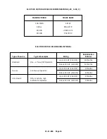
Motor Protective Devices
-- Overload heaters are
furnished for the starter in the voltage range specified.
There are three (3) overloads in the starter of proper
size for the starter and its enclosure. Note that motor
nameplate current must be multiplied by 0.577 for wye--
delta starters. The display will indicate that an overload
relay has tripped. The overload relay is reset by press-
ing the button on the relay itself, then the controller may
be reset. Motor current (amps) and voltage must be
measured in the affected motor wiring to locate the
cause for high current. Proper starter coil and contact
action is also monitored and errors in operation will
cause a shutdown with the cause displayed as a starter
or contact error.
High Temperature
-- The compressor is protected
from high discharge temperature by a thermistor probe
located in the compressor discharge.
The AUTO
SENTRY
R
-- W will shut the compressor down if temper-
ature exceeds 190
_
F (88
_
C) (or lower per user adjust-
ment) or if rapid temperature rise is detected. Shut-
down will also occur if the temperature falls below
freezing. The thermistor probe is also checked for
open or shorted circuits, and the display will indicate a
fault, if found.
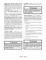
Machine damage will occur if com-
pressor is repeatedly restarted after
high temperature stops operation.
Find and correct the malfunction be-
fore resuming operation.
Water Filter Differential Pressure
-- The pressure
drop across the water filter is continually monitored by
the AUTO SENTRY
R
-- W. The unit will be shut down at
a differential pressure of approximately 40 psid (2.8
bars). This becomes active only after the compressor
has been running and pressures have had time to stabi-
lize.
The pressure drop can be monitored at any time by se-
lecting the alternate display “DIF PRES” (water filter
differential pressure) with the [?] HELP key. This
should be checked while the compressor is delivering
at full capacity. A service advisory comes on to recom-
mend maintenance prior to this shutdown.
High Water Level
-- If the water management controls
are unable to maintain proper water levels, the com-
pressor will shutdown to prevent damage. Check wir-
ing and piping of the drain and fill solenoid valves. A
shutdown also occurs if wiring errors are detected in
the float switch, and the display will indicate a bad float
switch.
Содержание ROTORCHAMP RCOF20
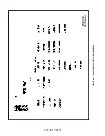
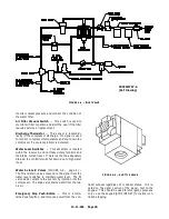
Страница 13: ...13 11 605 Page 4 FIGURE 1 6 AIR WATER SCHEMATIC 300EWC797 B Ref Drawing ...
Страница 16: ...13 11 605 Page 7 DECALS 206EAQ077 300EWC077 301EWC077 211EAQ077 207EAQ077 ...
Страница 17: ...13 11 605 Page 8 DECALS 216EAQ077 206EWD077 222EAQ077 221EAQ077 208EAQ077 ...
Страница 31: ...13 11 605 Page 22 FIGURE 4 2 FLOW CHART FOR SET UP PROGRAMMING 300EWC1255 Ref Drawing ...
Страница 41: ...13 11 605 Page 32 FIGURE 4 6 CONTROL TUBING SCHEMATIC 300EWC797 B Ref Drawing ...
Страница 43: ...13 11 605 Page 34 FIGURE 4 8 CONTROL SCHEMATIC COMPRESSOR UNLOADED CONSTANT SPEED MODE 303EWC797 A Ref Drawing ...
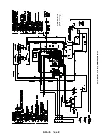
Страница 45: ...13 11 605 Page 36 FIGURE 4 10 WIRING DIAGRAM FULL VOLTAGE 301EWC546 A Ref Drawing ...
Страница 46: ...13 11 605 Page 37 FIGURE 4 11 WIRING DIAGRAM WYE DELTA 302EWC546 A Ref Drawing ...
Страница 47: ...13 11 605 Page 38 FIGURE 4 12 AUTO SENTRY W CONTROLLER DISPLAY ...
Страница 49: ...13 11 605 Page 40 FIGURE 5 1 OIL LEVEL SIGHT GLASS 306EWC797 A Ref Drawing ...
Страница 50: ...13 11 605 Page 41 FIGURE 5 2 FLOW DIAGRAM AIR COOLED 300EWC797 A Ref Drawing ...


