14 Servicing & Parts Replacement
46
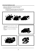
4. Remove the platform by removing the 4 Allen-bolts on top.
5. Remove the 4 screws on the corners of the uppercase.
6. Remove the key board:
A. Remove the 2 keyboard screws on top of the upper case.
B. Remove the keyboard grounding screw on the Main PCB.
C. Unplug the keyboard cable from J7 on the Main PCB.
7. Open printer side-door and remove 2 printer-
bay screws.
8. Remove the 3 screws in the keyboard access
area.
9. Then remove the upper case by sliding it
upwards.
Содержание LP-2G
Страница 2: ......
Страница 8: ......
Страница 11: ...1 General 3 Note Specifications are subject to change without notice ...
Страница 46: ...11 Network Options 38 11 Network Options Refer to Network manual ...
Страница 66: ...16 Troubleshooting 58 16 2 Versioning Changes ...
Страница 69: ...17 Schematic Diagrams 61 17 3 Main PCB ...
Страница 70: ...17 Schematic Diagrams 62 17 4 Ethernet Memory Expansion PCB ...
Страница 71: ...17 Schematic Diagrams 63 17 5 Power Supply PCB ...
Страница 72: ...18 Exploded Views 64 18 Exploded Views 18 1 Scale ...
Страница 73: ...18 Exploded Views 65 18 2 Printer Assembly ...
Страница 74: ......
Страница 89: ...Appendix C 85 ...
Страница 90: ...Appendix C 86 ...
Страница 91: ...Appendix C 87 ...
Страница 92: ...Appendix C 88 ...
Страница 93: ...Appendix C 89 ...
Страница 94: ...Appendix C 90 ...
Страница 95: ...Appendix C 91 ...
Страница 96: ...Appendix C 92 ...
Страница 97: ...Appendix C 93 ...
Страница 98: ...Appendix C 94 ...
Страница 99: ...Appendix C 95 ...
Страница 100: ...Appendix C 96 ...
Страница 101: ...Appendix C 97 ...
Страница 102: ...Appendix C 98 ...
Страница 103: ...Appendix C 99 ...
Страница 104: ...Appendix C 100 ...


