


69
minimum position/minimum cfm, then the evaporator dis
-
charge temperature (EDT) will be monitored. If the EDT falls
below a particular trip point then tempering mode may be
called out:
HVAC mode = “Tempering Vent”
HVAC mode = “Tempering LoCool”
HVAC mode = “Tempering HiCool”
The decision making/selection process for the tempering trip
set point is as follows:
If an HVAC cool mode is in effect, then the tempering cool
point is
SASP – T.CL
.
If not in effect and unit is in a pre-occupied purge mode (
Oper
-
ating Modes
MODE
IAQ.P
=ON), then the trip point is
T.PRG
.
If not in effect and unit is in an occupied mode (
Operating
Modes
MODE
IAQ.P
=ON), then the trip point is
TEMPVOCC.
For all other cases, the trip point is TEMPVUNC.
NOTE: The unoccupied economizer free cooling does not
qualify as an HVAC cool mode, as it is an energy saving fea
-
ture and has its own OAT lockout already. The unoccupied free
cooling mode (HVAC mode = Unocc. Free Cool) will override
any unoccupied vent mode from triggering a tempering mode.
A minimum amount of time must pass before calling out any
tempering mode. In effect, the EDT must fall below the trip
point value –1°F continuously for a minimum of 2 minutes. Al
-
so, at the end of a mechanical cooling cycle, a 10
-
minute delay
will be enforced before considering a tempering during vent
mode in order to allow any residual cooling to dissipate from
the evaporator coil.
If the above conditions are met, the algorithm is free to select
the tempering mode (MODETEMP).
If a tempering mode becomes active, the modulating heat source
(staged gas, modulating gas, SCR electric heat, or hot water) will
attempt to maintain leaving-air temperature (LAT) at the temper
-
ing set point used to trigger the tempering mode. The technique
for modulation of set point for staged gas, modulating gas, SCR
electric heat, and hydronic heat is the same as in a heat mode.
More information regarding the operation of heating can be ref
-
erenced in the Heating Control section.
Recovery from a tempering mode (MODETEMP) will occur
when the EDT rises above the trip point. On any change in
HVACMODE, the tempering routine will re-assess the temper
-
ing set point, which may cause the control to continue or exit
tempering mode.
Static Pressure Control
Variable air volume (VAV) air-conditioning systems must pro
-
vide varying amounts of air to the conditioned space. As air
terminals downstream of the unit modulate their flows, the unit
must simply maintain control over duct static pressure in order
to accommodate the needs of the terminals, and therefore to
meet the varying combined airflow requirement. The unit de
-
sign includes an optional means of accommodating this re
-
quirement. This section describes the technique by which this
control takes place.
A unit intended for use in a VAV system can be equipped with
a variable frequency drive (VFD) for the supply fan. The speed
of the fan can be controlled directly by the
Comfort
Link con
-
trols. A duct static pressure transducer is located in the auxilia
-
ry control box. The signal from the pressure sensor is received
by the RCB board and is then used in a PID control routine that
outputs a fan speed to the VFD.
The PID routine periodically calculates the static pressure error
from set point. This error at any point in time is simply the duct
static pressure set point minus the measured duct static. It is the
Proportional term of the PID. The routine also calculates the
Integral of the error over time, and the Derivative (rate of
change) of the error. A calculated value is then used to create
an output signal used to adjust the VFD to maintain the static
pressure set point.
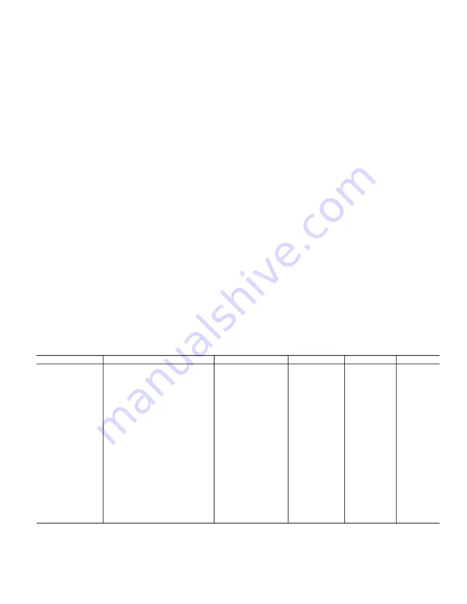
SETTING UP THE SYSTEM
Here are the options under the Local Display Mode
Configura
-
tion
SP
. See Table 46.
Table 46 —
Static Pressure Control Configuration
ITEM
EXPANSION
RANGE
UNITS
CCN POINT
DEFAULT
SP
SUPPLY STATIC PRESS.CFG.
SP.CF
Static Pressure Config
Disable/Enable
STATICFG
Disable
SP.SV
Staged Air Volume Ctrl
Disable/Enable
STATICFG
Disable
SP.S
Static Pressure Sensor
Disable/Enable
SPSENS
Disable
SP.LO
Static Press. Low Range
–10 to 0
in. wg
SP_LOW
0
SP.HI
Static Press. High Range
0 to 10
in. wg
SP_HIGH
5
SP.SP
Static Pressure Setpoint
0 to 5
in. wg
SPSP
1.5
SP.MN
VFD Minimum Speed
10 to 100
%
STATPMIN
20
SP.MX
VFD Maximum Speed
0 to 100
%
STATPMAX
100
SP.FS
VFD Fire Speed Over.
0 to 100
%
STATPFSO
100
SP.RS
Stat. Pres. Reset Config
0 to 4
SPRSTCFG
0
SP.RT
SP Reset Ratio
0 to 2.00
in. wg
SPRRATIO
0.2
SP.LM
SP Reset Limit
0 to 2.00
in. wg
SPRLIMIT
0.75
SP.EC
SP Reset Econo.Position
0 to 100
%
ECONOSPR
5
S.PID
STAT.PRESS.PID CONFIGS
SP.TM
Static Press. PID Run Rate
5 to 120
sec
SPIDRATE
7
SP.P
Static Press. Prop. Gain
0 to 5
STATP_PG
0.5
SP.I
Static Pressure Intg. Gain
0 to 2
STATP_IG
0.5
SP.D
Static Pressure Derv. Gain
0 to 5
STATP_DG
0.3
Содержание WeatherExpert 48N2
Страница 135: ...135 Fig 18 48 50N Typical Power Schematic Nominal 075 Ton Unit Shown ...
Страница 136: ...136 Fig 19 48 50N Typical Power Schematic Nominal Ton 90 150 Units Shown ...
Страница 137: ...137 Fig 20 48 50N Main Base Board Input Output Connections ...
Страница 138: ...138 Fig 21 48 50N RXB EXB CEM Input Output Connections a48 9307 ...
Страница 139: ...139 Fig 22 48 50N EXV SCB Input Output Connections a48 9308 ...
Страница 140: ...140 Fig 23 48N Typical Modulating Gas Heat Unit Control Wiring ...
Страница 141: ...141 Fig 24 50N Typical Electric Heat Unit Control Wiring ...
Страница 144: ...144 Fig 27 48N Typical Gas Heat Section Wiring Nominal Ton 120 to 150 Units ...
Страница 145: ...145 Fig 28 48 50N Typical Power Component Control Wiring 460 v ...
Страница 146: ...146 Fig 29 48 50N Component Control Wiring 575 v Nominal Ton 075 to 150 Units ...
Страница 147: ...147 Fig 30 48 50N Component Arrangement Power Box ...
Страница 148: ...148 Fig 31 48 50N Component Arrangement Control Box ...
Страница 168: ...168 Fig 47 Sensor and Ignition Position Fig 48 Combustion Blower Details SENSOR DETAILS IGNITION DETAILS ...
Страница 240: ...240 APPENDIX D VFD INFORMATION CONT Fig G VFD Bypass Wiring Diagram WHEN USED ...


