


MN702GE 060320
– 20 –
Step 1
Check gas pilot operation
The Model 702GAS uses a gas pilot for ignition of the gas
main flame. The gas pilot is ignited by the pilot electrode. The
butterfly gas valve is factory set to a preliminary setting of 30%
open for low fire, and 100% open for high fire.
1.
Make sure the gas line has been completely bled. Then turn the service
switch to ON.
2.
The pilot will usually light the first time once the pilot gas train has been
completely purged of air.
3.
The pilot flame is approximately 70 MBH. If the pilot fails to light, be sure
the gas line has been bled properly. If the primary control is equipped
with a pilot test hold switch, it can be used to hold the pilot “on” while
adjusting pilot gas pressure.
4.
Follow the instructions in the primary control instruction manual to check
flame signal. Make sure the flame signal is steady, and greater than the
required minimum for the UV sensor.
5.
Check and ensure that the bent ignitor (Figure 11) is approximately
centered in pilot assembly.
6. To check static pressure on pilot air, drill a #60 hole in the pilot air tube
(red circle, Figure 12) and use a manometer for the reading. Pressure
must be more than .45” w.c.
Step 2
(firing on gas)
Set main gas pressure regulator
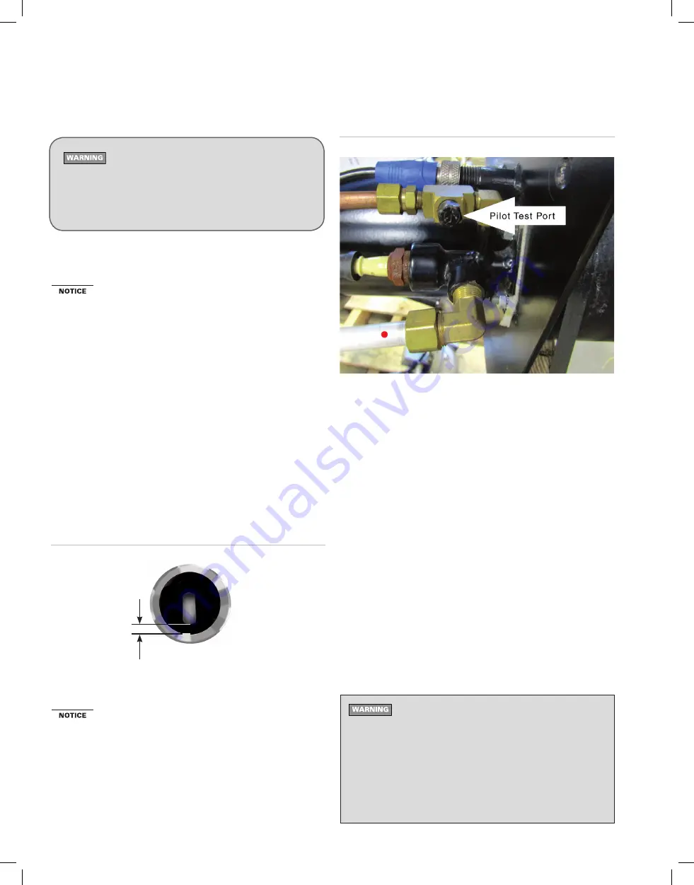
The butterfly gas valve is factory set to a preliminary setting of
30% open for low fire, and 100% open for high fire. The pilot
regulator is set for 3.0 inches w.c. Use manometer in the pilot
test port (Figure 12) provided to confirm settings.
1.
Leave the low-fire switch in low fire.
2.
With the gas pilot operating correctly, and the UV sensor flame signal
above minimum required, the primary control will cycle the burner to
main gas.
7. Adjust the burner using test instruments
(continued)
Check all joints with a soap suds mixture or electronic
gas leak detector to ensure the gas train and all compo-
nents are tight and leak-free. Shut down the burner and
correct any leak immediately. Failure to comply could
result in severe personal injury, death or substantial
property damage.
3.
Check the flame signal after the pilot has shut down to ensure the signal
is still strong with main flame on.
4.
Move the burner fuel selector switch to OFF. The burner will shut down.
5.
Temporarily install two U-tube manometer connections to check gas pres-
sures. Install connections at the inlet pressure tap of the main manual
gas valve and at the downstream pressure tap of the manual gas valve
next to the butterfly valve.
6.
The gas pressure at the inlet to the gas train must never exceed
14 inches w.c., either when the burner is off or firing on gas.
7.
Move the burner fuel selector switch to GAS. The burner should start.
8.
With the burner firing in low fire, check the gas pressure at the downstream
of the butterfly valve. Adjust the main gas pressure regulator if necessary
until the gas pressure reads 1.0 inch w.c. as a starting pressure.
9.
Switch the low-fire switch to high fire. CAUTION: Be prepared to turn
the burner off immediately if it begins to pulsate as it attempts to move
to high fire.
10.
If the flame pulsates, it is probably too rich. Switch the low-fire switch to
low fire and reduce the gas pressure by adjusting the main gas pressure
regulator. Then return to 9, above.
11.
If the fire is too lean, it will appear small and can even blow out during the
swing to high fire. If it blows out, shut off the burner immediately. Switch
the low-fire switch to low fire and start the burner again. Adjust the main
gas pressure regulator to increase the gas pressure. Return to 9, above.
With the burner running in high fire, inspect the buttefly
valve indicator (Figure 13). The indicator must be at 90°.
IF NOT, turn the burner off. Loosen the two hex-head
screws securing the valve linkage arm. With the damper
motor linkage arm pulled up, use a screwdriver to rotate the
butterfly valve slot until it is horizontal. Tighten the two hex
head screws while still holding the damper motor linkage
arm up. Return to step 9, above. DO NOT proceed with
combustion adjustment unless the butterfly valve position
has been verified, and corrected if necessary.
Figure 12
Pilot Test Port
Figure 11
Pilot Spark Gap
3/32"-1/8"