Carlin 702GAS Скачать руководство пользователя страница 12

MN702GE  060320

– 12 –

2.  Pre-fire inspection  •  preparation 

(continued)

Install gas train on burner

1.  The standard burner gas train is shipped fully assembled, with the piping 

disconnected at the gas train unions. See separate instructions if installing 

an optional knocked down gas train. The gas train is available in either 

an angled (standard) or straight (optional) configuration.

2.  Connect the main trains at the unions (Figure 5).

  To avoid damage to gas train components, do not hold compo-

nents with a pipe wrench or overtighten. Use only a crescent 

wrench or other means. Failure to comply could result in severe 

personal injury, death or substantial property damage.

3.  Connect the flexible conduit, pre-attached to the burner J-box, to the gas 

train J-box, and attach the wires to the terminal strip inside the gas train 

J-box.

a. 

Match wire colors of the incoming wires to those pre-wired to the 

terminal strip inside the gas train J-box.

b. 

See the label in the burner junction box included

  Gas valve vent opening — The V48 diaphragm gas valve is 

NOT fitted with a vent limiting orifice in the vent connection. If 

local codes require, install piping from the vent connection to 

outside, sized and installed as required by codes. Because this 

is a diaphragm-assisted solenoid valve, a small amount of gas 

will exit from the vent orifice each time the valve opens.
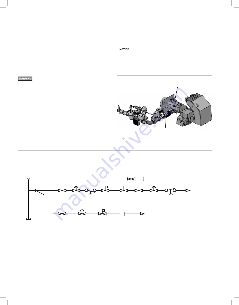
Figure 5 

Gas train installation (shown with straight gas train)

Connect pilot gas train at union

Connect main gas train at union

Figure 5A 

Gas piping schematic

GAS FUEL TRAIN

OIL FUEL TRAIN

Gas Input

F

A

A

FS

P

R

A

M

Test

To Main Burner

To Pilot Burner

J

R1

B

S

R2

S

C

S

Sediment Trap

Oil Supply
Connection

Oil Return
Connection

U

V

W

Y

HF

LF

FS  Fuel Strainer 

Oil Pressure Interlock Switch (if required)

HF  High FIre Nozzle 

Low Fire Safety Shutoff Valve

LF  Low FIre Nozzle 

High FIre Safety Shutoff Valve

Fuel Pump 

Fuel Pressure Gauge (if required)

Mechanical Shutoff Valve


A  Manual Valve
B  Firing Rate Valve
C Orifice
D  Manual Reset Low Gas Pressure Switch (optional)

Manual Reset High Gas Pressure Switch (optional)

Gas Filter or Strainer (if required)

Leakage Test Valve

M  Pipe Cap
R1  Main Gas Pressure Regulator
R2  Pilot Gas Pressure Regulator
S  Safety Shutoff Valve

D

E

Содержание 702GAS

Страница 1: ...maintenance on back page for information regarding operation of this burner The burner Instruction Manual is intended only for your service technician The burner and heat exchanger must be inspected a...

Страница 2: ...heguidelinesbelowtoavoidpotentialsevere personal injury death or substantial property dam age Installer service technician Read all instructions before proceeding Perform all procedures and in the ord...

Страница 3: ...mply with the latest editions of Installation of Domestic Gas Conversion Burners ANSI Z21 8 National Fuel Gas Code ANSI Z223 1 NFPA 54 National Electrical Code ANSI NFPA 70 All additional applicable n...

Страница 4: ...into the burner through a manifold around the air tube The gas then circulates through a set of four orifice spuds into the air stream upstream of the retention ring The spin of the air flow at the re...

Страница 5: ...0 Btuh of all appliances in the space Do not install or operate the burner if any component is dam aged or if burner does not comply with other guidelines of this manual and the appliance manual Inspe...

Страница 6: ...u facturer s instructions Wire the switch into the appliance limit circuit to shut off the appliance burner if sustained downdraft should occur Refer to the appliance manufacturer s instruction manual...

Страница 7: ...2 Metal louvers or grilles free area area times 0 60 3 Screens when used must be no smaller than inch mesh Motorized vent dampers Wire the vent damper end switch to prevent operation of the burner un...

Страница 8: ...ications Whenfiringwithpositive overfire pressure do not exceed the pressure specified in the appliance manual Positive overfire pressure reduces maximum burner capacity See Page 3 for estimated reduc...

Страница 9: ...e a floor liner when possible The floor liner will improve firing in most applications Extend floor liner 3 to 4 inches up the side walls 4 Target wall liners Extend target wall liners at least 3 to 4...

Страница 10: ...ance opening so the end of the air tube is flush with or slightly short of the inside surface of the combustion chamber 4 Place gasket onto boiler front plate 5 Slide the end of the air tube into the...

Страница 11: ...enough ventilation to prevent overheating of the appliance burner and controls If there is risk of overheating you must install ventilation air openings sized large enough to provide air for cooling t...

Страница 12: ...e terminal strip inside the gas train J box b See the label in the burner junction box included Gas valve vent opening The V48 diaphragm gas valve is NOT fitted with a vent limiting orifice in the ven...

Страница 13: ...be more than the gas pressure at the burner gas train en trance minus 3 4 w c pressure required at entrance to butterfly valve See Figure 6 for gas train pressure drop information The standard gas tra...

Страница 14: ...990 810 690 620 2 2 750 1 900 1 520 1 300 1 150 2 4 350 3 000 2 400 2 050 1 850 Note 1 For natural gas with specific gravity other than 0 60 consult National Fuel Gas Code for correction factor PROPAN...

Страница 15: ...rmation for burner equipped with a primary control not covered in this manual see Figure 7A for a legend to callouts Turn off power to appliance when servicing burner Failure to comply could result in...

Страница 16: ...steam boiler activated Read the appliance manual for the location of the high fire control when used 3 See Figures 7 and 8 to connect the high fire control to the burner firing rate circuit 4 The burn...

Страница 17: ...nuals and wiring diagrams Gas manifold spud orifices sealed with pipe dope and tight Gas lines in good condition sized and designed correctly Gas line connections and fittings tight Burner appliance a...

Страница 18: ...et air damper linkage Table 5 Initial burner settings see the pages 18 through 22 for final adjustments using test instruments 6 Set burner initial head and damper positions continued 3 4 Determining...

Страница 19: ...e the maximum burner firing rate is reduced The firing rate is also reduced for altitudes higher than 2000 feet above sea level See page 3 for rating information 3 Adjust the burner fuel and air setti...

Страница 20: ...personal injury death or substantial property damage 3 Check the flame signal after the pilot has shut down to ensure the signal is still strong with main flame on 4 Move the burner fuel selector swi...

Страница 21: ...ly valve indicator until it is at 90 Disengage actuator motor Rotate linkage to high fire Tighten the two hex head screws while still holding the motor linkage arm in high fire Rotate linkage to low f...

Страница 22: ...ion with exhaust fans or other conditions operating 7 Adjust the burner using test instruments continued Combustion ventilation air Verify combustion ventilation air openings are not and will not be o...

Страница 23: ...s valves before disconnecting any portion of fuel lines and before cleaning or removing any parts from the burner or related equipment Burner and appliance components can be extremely hot Allow all pa...

Страница 24: ...season and to verify user is aware of proper operation and care of the burner appliance Review proper operation of the appliance burner unit with the user Turn off power to appliance Remove combustion...

Страница 25: ...Btuh Manifold gas pressure IWC High fire Low fire Inlet gas pressure IWC CO2 Gas Low Fire ______ Gas High Fire ______ Gas Low Fire ______ Gas High Fire ______ O2 Were limit controls tested Comments ab...

Страница 26: ...4 Combustion Head Assembly for 702GAS 7 4180002FS Gas Ignitor 8 35824S Motor Contactor 20 AMP R4242B1005 not shown ITEM PART NO DESCRIPTION 9 35311S C7027A1023 UV Scanner 97656S Q7800B1003 Sub Base 99...

Страница 27: ...appliance burner unit NEW PHOTO TO COME ITEM PART NO DESCRIPTION 16 35824S Motor Contactor 20 AMP R4242B1005 19 EMX51UVS EMX51UV KIT includes all of the below 35311S C7027A1023 UV Scanner 97656S Q780...

Страница 28: ...MN702GE 060320 28 10 Dimensions Figure 14 Dimensional data...

Страница 29: ...MN702GE 060320 29 10 Dimensions continued Figure 14A Dimensional data angled gas train...

Страница 30: ...and liquids Do not obstruct the flow of combustion and ventilating air Most motors currently used on residential type burners use permanently lubricated bearings and do not require field lubri cation...

Отзывы: