


MN702GE 060320
– 13 –
3. Install gas piping
Connect from the gas supply to the burner gas train
inlet using new, clean black iron pipe and malleable
iron fittings only. Do not use copper, brass, cast iron
or galvanized pipe or fittings.
Provide support for gas piping. Do not rest the weight
of the gas piping on burner gas train.
Provide a support for the burner gas train.
Apply pipe dope sparingly at all joints. Use only pipe
dope listed for use with propane gas. Do not use pipe
sealing tape.
Do not hold the gas valve with pipe wrench. Use
crescent wrench or other smooth-jawed device. Do
not overtighten.
Failure to comply with above could result in severe
personal injury, death or substantial property damage.
Do not expose the gas train to gas pressure in
excess of 14 inches water column. Higher pressure
could damage the valve seat, resulting in potentially
hazardous condition. When pressure testing piping
at higher pressures, disconnect burner from gas line
before testing.
If the gas supply pressure can exceed 14 inches water
column at any time, you must install a lockup type gas
pressure regulator in the gas supply piping, ahead of
the main manual gas valve installed at the burner.
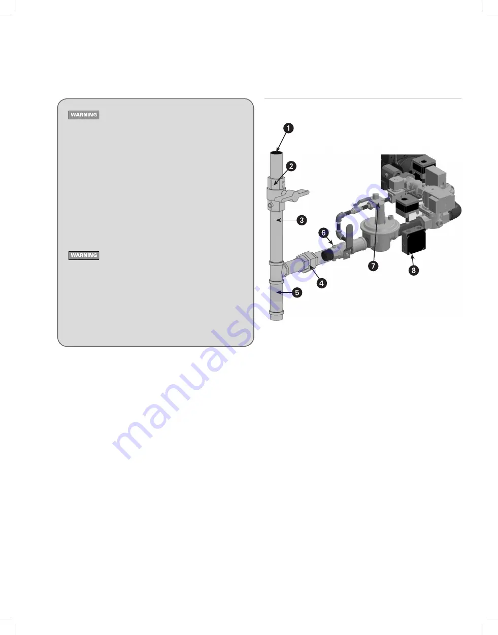
Figure 5A
Connecting gas supply piping to burner
(shown with angled gas train)
Piping from gas meter to burner
1. Verify the gas train on the burner is correctly sized. The gas train pres¬sure
drop must not be more than the gas pressure at the burner gas train en-
trance minus 3.4" w.c. (pressure required at entrance to butterfly valve).
See Figure 6 for gas train pressure drop information. The standard gas
train is 1 inch.
2. If possible, install a new gas line directly from the gas meter. If you are
using an existing gas line, verify it is clean and in good condition, and
verify it is large enough to handle the load of all connected appliances.
3. When branching from a common gas line, do not tap off from the bottom
of horizontal sections – only from the side or top.
4. Install a main manual shutoff valve, sediment trap and ground joint union
near the burner gas train connection as shown in Figure 5A.
5. If the burner is installed inside an appliance jacket, install the main manual
gas valve and sediment trap external to the jacket.
6. Size piping (or verify size) using Table 3. You will find additional informa-
tion on gas line sizing in the National Fuel Gas Code, ANSI Z223.1.
Gas supply pressure – natural gas or propane Maximum supply pressure:
14 inches w.c.
Minimum supply pressure: 5 inches w.c.
Test and purge gas line
Read WARNING above.
Pressure test and purge the line. Pressure testing should be done by the gas
supplier or utility, following all applicable codes.
1 Pipe to meter or branch
2 T-handle main manual gas valve
3 Use clean, burr-free black iron
pipe and malleable iron fittings
4 Ground joint union
5 Sediment leg
6 Pressure tap, 1/4" (upstream
shown, outlet not shown)
7 Gas regulator access screw
(the regulator spring is located
under the adjusting screw)
8 Gas train wire junction box