


MN702GE 060320
– 19 –
Adjustment procedure, summary
Step 1: Set gas pilot operation. See details following.
Step 2 Set high-fire gas flow to match high-fire air. See details following.
Step 3 Adjust the butterfly valve linkage to match low-fire gas to low-fire
air. See details following.
Step 4: Verify operation of burner, appliance, and controls.
Use test instruments
1.
Use combustion test equipment and an accurate manometer or draft
gauge to correctly set the burner as required.
2.
Overfire pressure must not exceed the appliance manufacturer’s recom-
mendations. The burner must never be fired at an overfire pressure more
than 0.60 inches w.c.
When the overfire pressure is positive, the maximum burner
firing rate is reduced. The firing rate is also reduced for
altitudes higher than 2000 feet above sea level. See page 3
for rating information.
3.
Adjust the burner fuel and air settings using the following procedures.
When adjustment has been completed, the CO
2
(or O
2
) should be within
the ranges in Table 6, at both low fire and high fire.
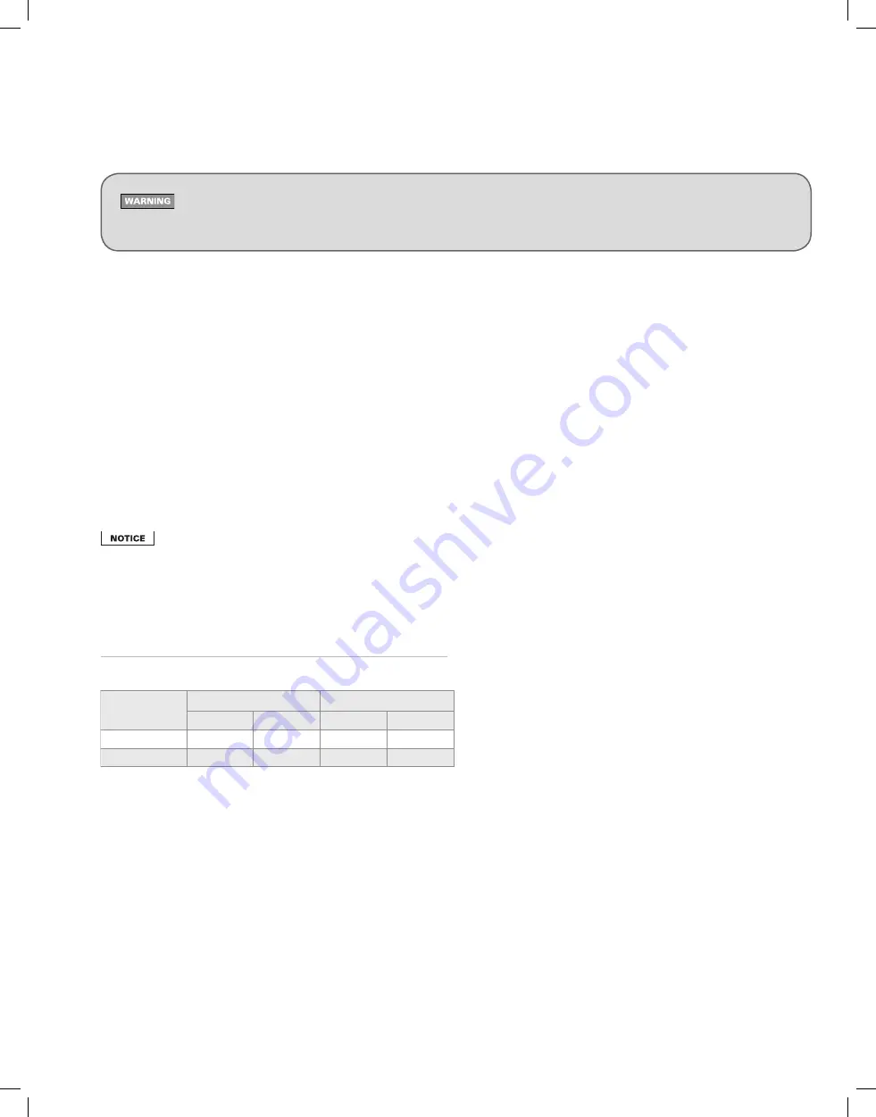
Table 6
Allowable values of CO
2
and O
2
Fuel
CO
2
O
2
Minimum Maximum Maximum Minimum
Natural Gas
8.5 %
10.0 %
6.2 %
3.6 %
Propane
9.5 %
11.2 %
6.0 %
3.5 %
7. Adjust the burner using test instruments
The settings given in Section 6 are initial settings only. You must use test instruments to check combustion, and adjust the burner
as necessary, following the procedures given in the following pages of this manual. Failure to properly adjust the burner can result in
severe personal injury, death or substantial property damage.