


MN702GE 060320
– 18 –
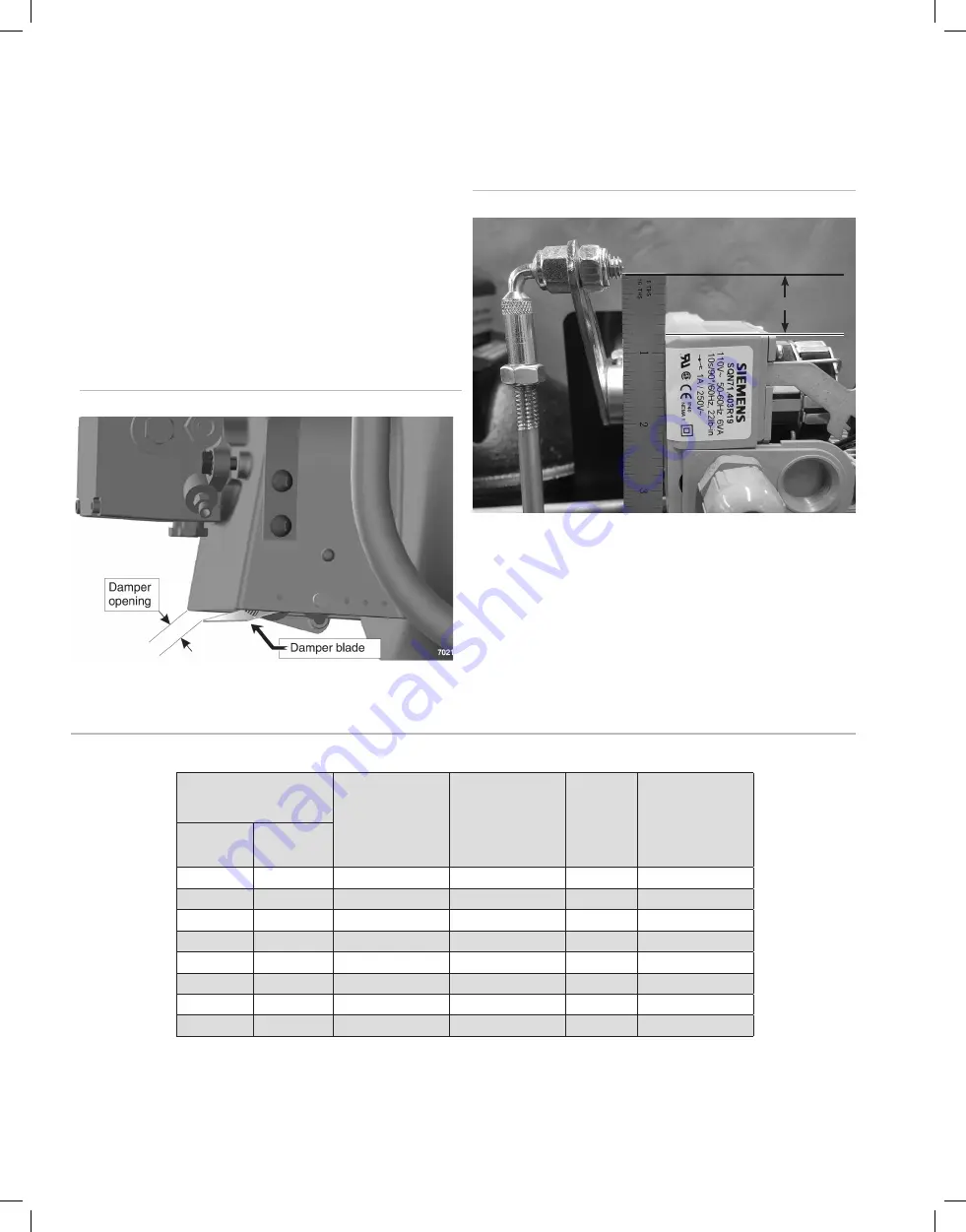
Set air damper (low fire position)
See Figure 10. Adjust the blue cam on damper motor until the air opening
between the damper blade and the damper housing equals the initial low-fire
opening in Table 5.
Set air damper linkage
Make sure Air Damper Linkage is set at ¾" from the top of the Damper Motor
and the bottom of the linkage screw (see Figure 10A). If your settings are off,
loosen the two hex head screws found on the linkage arm bosses at the top
and bottom of the Air Damper Linkage. Adjust the linkage accordingly, then
tighten screws to set position.
Figure 10
Set initial low fire air damper setting
Figure 10A
Set air damper linkage
Table 5
Initial burner settings (see the pages 18 through 22 for final adjustments using test instruments)
6. Set burner initial head and damper positions
(continued)
3/4
"
Determining final adjustments
The burner is now adjusted to the approximate air settings for the firing rate
used. Follow the procedures on the following pages to use test instruments
and make final burner adjustments.
Natural Gas MBH
Combustion head
position
Dimension “A”
Inches (approximately)
Air damper low-fire
opening
Inches (approximately)
Siemens
Blue Cam
Setting
Butterfly valve
open – low fire
(factory set)
% (approximately)
Low-fire
Input
High-Fire
Input
490
840
0
3/8
25
30
525
910
1/16
3/8
25
30
560
966
1/8
7/16
27
30
630
1092
3/16
7/16
27
30
700
1218
3/8
1/2
30
30
770
1330
5/8
1/2
30
30
840
1456
1-1/8
9/16
35
30
910
1568
1-3/8
9/16
35
30