13
ENG
Hecu
C
O
2
+0300085EN rel. 2.2 - 07.05.2019
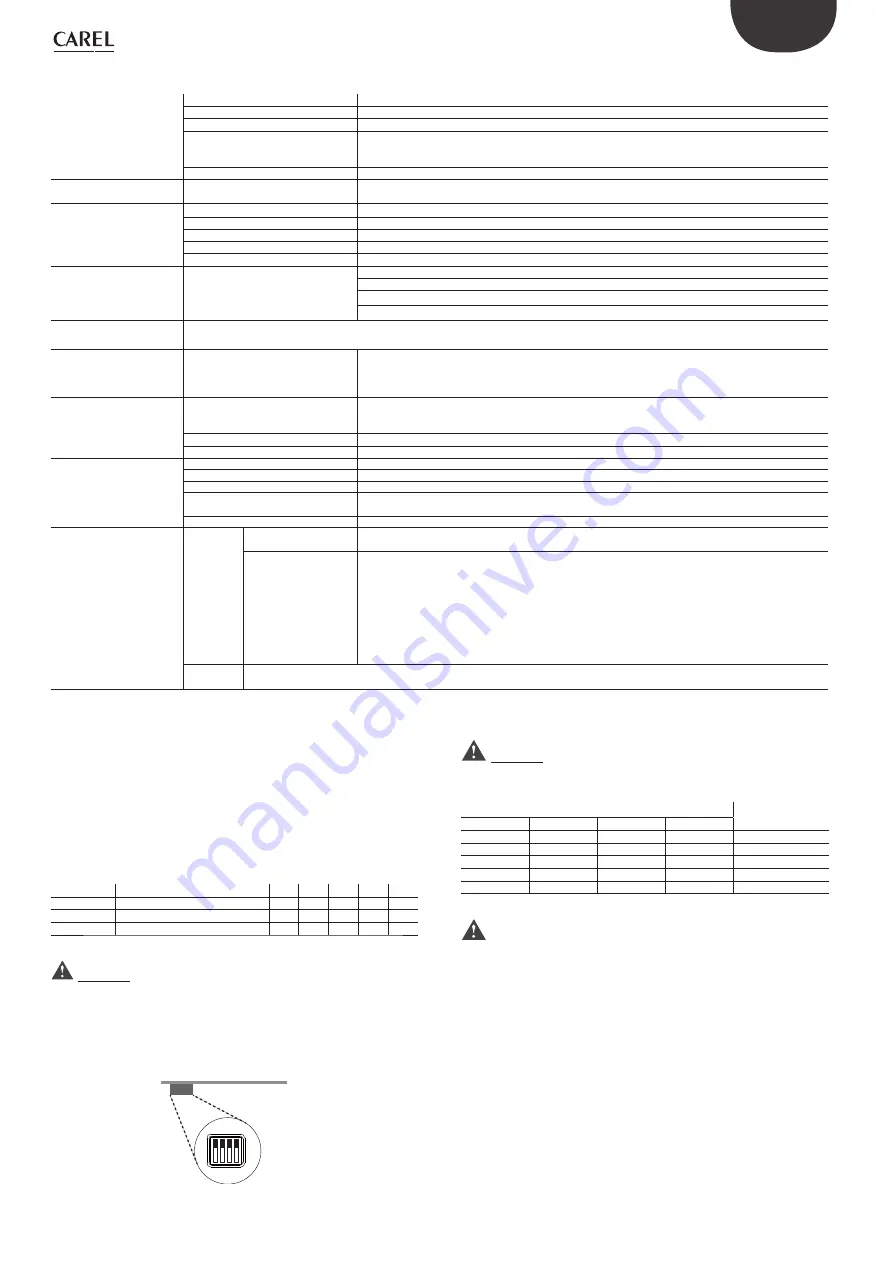
Main technical specifi cations
Environmental conditions
Storage temperature
-40T60°C
Operating temperature
-20T60°C
Humidity
< 95% RH non-condensing
Altitude
Maximum allowed: 2000 m above sea level
Up to 1000 m asl without derating
Derating in terms of maximum output current: 1% /100m
Environmental pollution level
3
Power supply
Input voltage
PS2**183*****, PS2**243*****: 200 - 240Vac -10%/ +10%, 50 - 60Hz, 3 ~
~
PS2**184*****, PS2**244*****: 380 - 480Vac -10%/ +10%, 50 - 60Hz, 3 ~
~
Motor output
Output voltage
0 - Input voltage
Output frequency
0 - 500 Hz
Frequency resolution
0.1 Hz
Maximum cable length
see paragraph 5.1
Switching frequency
4, 6, 8 kHz
Functions
Protection functions
Drive: short circuit, overcurrent, earth fault, overvoltage and undervoltage, overtemperature
Motor: overload (150% Inom for 1 minute), stall
System: loss of communication,
Safety: STO (Safe Torque Off ), locked rotor
Control unit
Each drive must be connected in the network via Modbus® to a CAREL pCO or other manufacturer’s controller that manages the drives with
Master/Slave logic.
Inputs
STO (Safe Torque Off )
Voltage-free contact input, reinforced insulation (24 V SELV circuit):
open contact voltage: <24 V
closed contact current: 40 mA typical
max. cable length 25 m
Interface
connection
data
Serial data connection
RS485, Modbus® protocol, maximum baud rate 19200 bit/s
Typical reception resistance 96 KΩ, equal to 1/8 of unit load, i.e. 1/256 of maximum load applicable on
the line
Insulation
Reinforced (24 V SELV circuit)
Maximum length
100 m shielded cable
Other
Ingress protection
IP00
Ball pressure test temperature
125°C
Construction
Device to be incorporated
Type of automatic action
PS2********0* and PS2********S* models: Type 1 (functional control)
PS2********1* and PS2********P* models: Type 2 (safety control)
Pulse voltage
4 kV (overvoltage category III)
Standards
compliance
CE
Low voltage directive
2014/35/EU
IEC 60730-1, IEC 60335-1 (sections 29 and 30), IEC 60335-2-34 (sections 19.101 and 19.103)
Electromagnetic com-
patibility directive
2014/30/EU
EN 61800-3, ed.2.0: Adjustable speed electrical power drive systems. EMC requirements, including
specifi c test methods.
EN61000-3-2: Electromagnetic compatibility (EMC) Part 3-2: Limits - Limits for harmonic current emis-
sions (equipment input current <= 16 A per phase).
EN61000-3-12: Electromagnetic compatibility (EMC) Part 3-12: Limits - Limits for harmonic current emis-
sions (equipment input current > 16 A and <=75 A per phase).
UL
UL 60730-1, UL 60335-1 (sections 29 and 30), UL 60335-2-34 (sections 19.101 and 19.103). See chap. "UL requirements for installa-
tion".
Tab. 2.l
Network address
The confi guration and programming of the Power+ drive, as well as the
run/stop commands and speed reference, are managed by a CAREL pCO
controller or by any BMS (Building Management System) via RS485 serial
connection with Modbus® protocol. The ModBus® network address can
be set from 1 to 246, and this number comprises the basic address set by
parameter, and the address set by the 4 dipswitches inside the drive, from
0 to 15. By changing the basic address, it is possible to cover the entire
range of addresses.
Mod. add.
Description
Def
Min
Max UOM R/W
32
Basic address
1
1
232
-
R/W
120
Network address
-
1
246
-
R
121
Dipswitch address
-
0
15
-
R
Tab. 2.m
Important:
any changes to the device’s serial address, either on the dipswitches or via
the parameter, will only be eff ective when next powering on or resetting
the device.
The confi guration of the address set manually by the dipswitches on the
drive is shown below.
1
ON
OFF
2
3
4
Fig. 2.j
Important: Before accessing the dipswitches, power off and wait for
the LEDs to go off .
Dipswitch address
Dipswitches
Dipswitch
address
1
2
3
4
OFF
OFF
OFF
OFF
0
ON
OFF
OFF
OFF
1
OFF
ON
OFF
OFF
2
…
…
…
…
…
ON
ON
ON
ON
15
Tab. 2.n
Warning
: if the address set by the dipswitches is between 0 and 14,
the network address is the sum of the basic address and the dipswitch
address, while baud rate and parity are set by the corresponding
parameters.
If the dipswitch address is set to 15, communication mode is set to:
•
19200 bit/s; no parity; 2 stop bits; network address 1
regardless of the value of the corresponding parameters.
It is recommended to avoid setting the dipswitch address to 15 as a
normal confi guration.
Содержание Hecu CO2
Страница 2: ......
Страница 4: ...4 ENG Hecu CO2 0300085EN rel 2 2 07 05 2019...
Страница 6: ......
Страница 61: ...61 ENG Hecu CO2 0300085EN rel 2 2 07 05 2019 9 2 Software revision history New version 3 0 012...
Страница 62: ...62 ENG Hecu CO2 0300085EN rel 2 2 07 05 2019 Notes...
Страница 63: ......


